- Sun Sep 27, 2015 1:51 pm
#29993
Hi, I got a few of these off of ebay around the beginning of August and today I finally had the time to mess with them.
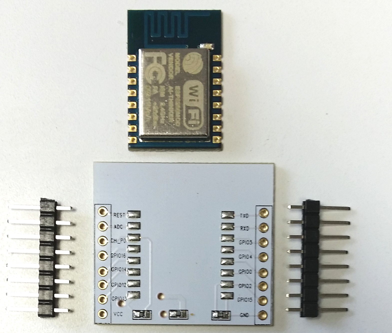
The package came with each module sealed in an anti-static bag and for each module, an expansion board+pin headers were also included, like in the picture below:
http://internetofhomethings.com/homethi ... -apart.jpgI found a bunch of websites detailing how to solder the module to the expansion board plus the connections to make in order to communicate with the module -
but three modules soldered, and no response at all on minicom.I was about to consider a faulty batch or something, when I noticed that the expansion boards had three connector holes towards the bottom left of the expansion board:
- one is right between the words GPIO13 and VCC
- the other two are vertically aligned, at center bottom of the board
Directly connecting the one between GPIO13/VCC and the vertically lowest of the other two made two modules work and I was able to flash them with nodeMCU:
- the flashing at 9600 baud rate did take its time though (several minutes operation)
- so far, a day has gone by and they keep on working
Still I'm not sure what those are for and my electronical skills aren't that solid as well.
Does anyone know what those connectors are for...? Did anyone else need to do anything similar to this to get the modules running...? Have I missed something with the setup?
I use minicom with S/W flow control off + 9600 baud to communicate with the modules, same settings as with ESP8266-01 which I also have and are running properly.


