
- Fri May 27, 2016 11:33 am
#48128
Testing your collective wisdom if you don't mind?
About the project...
I mess about with this kind of stuff, hacking I believe you call it I also have four bicycles in a garden shed and there is plenty of crime with bikes being sought after. I have upgraded my home security system so that the house is now IoT enabled. There is a Raspberry Pi embedded in the home security panel which interfaces using GPIO. Specifically I have a "System Armed" and "System Alarming" inputs to the Pi and I have the fire alarm circuit of the home security through a relay driven again by the Pi's GPIO.
The Pi is running Mosquitto and is the MQTT broker handling messaging between my Nodemcu and the Raspberry Pi.
I have some code working on the Nodemcu and the Pi and it is sweet. I set my home security and the shed security system automatically arms and acknowledges the arm message from the Raspberry Pi. All works well and I can simulate an intrusion to the shed and the shed security "alarms", via the MQTT link the house security also "alarms" and the Python code on the Pi uses bash/cURL to push (pushbullet) a message to my phone. Happy days!
So I have plenty experience with electrical/electronics and Pi's and Arduinos but this doesn't make sense. I have worked in the industrial automation business for years, this is all simple stuff but it won't work on external power! I am stumped!
If I power the Nodemcu via the USB then it starts and runs fine. If I plug the module on to the board below (with 5V from the buck converter to the 5V pin on the module) then it will stay running even if I remove the USB lead. If however I supply 5V through the module pins (no USB supply)... Nothing! There is power getting to the board via the 5V pin as the board regulates my 5V down to 3V3 using the on board linear reg.
If I power the module via the 3v3 pins it is just the same, I tried this, it won't start???
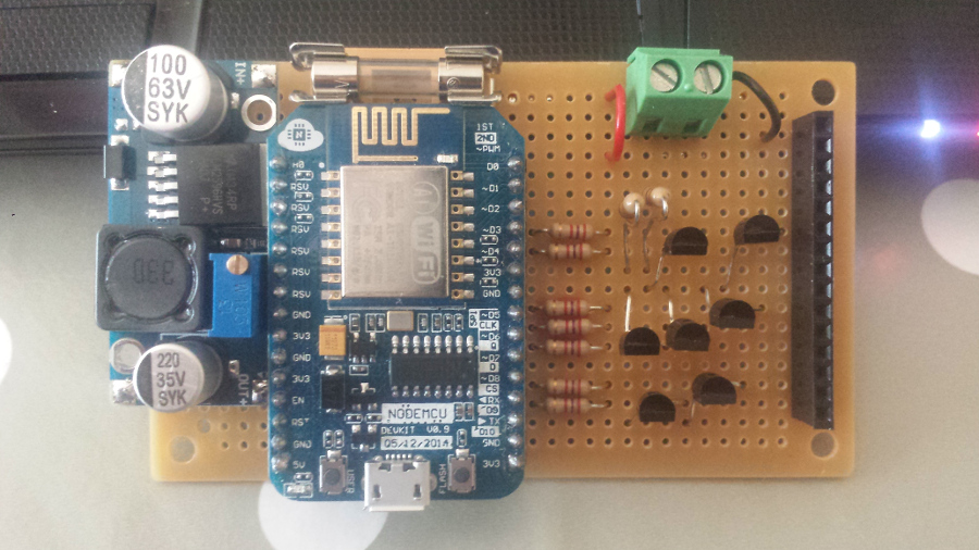
There's the board, all the I/O is on the right:
D0 - No connection (will be door magnetic reed switch)
D1 - Pull Up (10K) to 3v3 (reading row 2 of 4 x 3 matrix keypad)
D2 - Pull Up (10K) to 3v3 (reading row 4 of 4 x 3 matrix keypad)
D3 - Series resistor 1k8 to base of 2N2222 (polling column 1 of 4 x 3 keypad)
D4 - Series resistor 1k8 to base of 2N2222 (polling column 2 of 4 x 3 keypad)
3v3 - VCC used for D0, D1 pull up
GND - Emitter of 2N2222 of D3, D4, D5, D6, D7
D5 - Series resistor 1k8 to base of 2N2222 (RGB Red Led)
D6 - Series resistor 1k8 to base of 2N2222 (RGB Green Led)
D7 - Series resistor 1k8 to base of 2N2222 (RGB Blue Led)
D8 - No Connection
D9 - Series resistor 1k8 to base of 2N2222 (Piezo Buzzer)
D10 - Series resistor 1k8 to base of 2N2222 (105dB Piezo Siren)
GND - Emitter of 2N2222 of D9, D10
Am I missing something? The buck converter is good for 3Amps or so. I can probe the board and there is 3.3v on all the 3.3v pins, 5v on the 5v pin but I get no LED's on the Nodemcu? The fact that I have 5V on the board and the internal linear reg is supplying 3.3v to the pins tells me there is no short to ground. I just can't work out why the module does not boot? The whole system runs of 12Vdc solar/battery through the green screw terminal and yes, I take 12V out to the 105dB siren through the red/black wires and the header. The only other 12V connection is to the buck converter supply pads.
Any ideas? I would be much obliged if you can spot my mistake!!!
Thanks
Garry
About the project...
I mess about with this kind of stuff, hacking I believe you call it
The Pi is running Mosquitto and is the MQTT broker handling messaging between my Nodemcu and the Raspberry Pi.
I have some code working on the Nodemcu and the Pi and it is sweet. I set my home security and the shed security system automatically arms and acknowledges the arm message from the Raspberry Pi. All works well and I can simulate an intrusion to the shed and the shed security "alarms", via the MQTT link the house security also "alarms" and the Python code on the Pi uses bash/cURL to push (pushbullet) a message to my phone. Happy days!
So I have plenty experience with electrical/electronics and Pi's and Arduinos but this doesn't make sense. I have worked in the industrial automation business for years, this is all simple stuff but it won't work on external power! I am stumped!
If I power the Nodemcu via the USB then it starts and runs fine. If I plug the module on to the board below (with 5V from the buck converter to the 5V pin on the module) then it will stay running even if I remove the USB lead. If however I supply 5V through the module pins (no USB supply)... Nothing! There is power getting to the board via the 5V pin as the board regulates my 5V down to 3V3 using the on board linear reg.
If I power the module via the 3v3 pins it is just the same, I tried this, it won't start???
There's the board, all the I/O is on the right:
D0 - No connection (will be door magnetic reed switch)
D1 - Pull Up (10K) to 3v3 (reading row 2 of 4 x 3 matrix keypad)
D2 - Pull Up (10K) to 3v3 (reading row 4 of 4 x 3 matrix keypad)
D3 - Series resistor 1k8 to base of 2N2222 (polling column 1 of 4 x 3 keypad)
D4 - Series resistor 1k8 to base of 2N2222 (polling column 2 of 4 x 3 keypad)
3v3 - VCC used for D0, D1 pull up
GND - Emitter of 2N2222 of D3, D4, D5, D6, D7
D5 - Series resistor 1k8 to base of 2N2222 (RGB Red Led)
D6 - Series resistor 1k8 to base of 2N2222 (RGB Green Led)
D7 - Series resistor 1k8 to base of 2N2222 (RGB Blue Led)
D8 - No Connection
D9 - Series resistor 1k8 to base of 2N2222 (Piezo Buzzer)
D10 - Series resistor 1k8 to base of 2N2222 (105dB Piezo Siren)
GND - Emitter of 2N2222 of D9, D10
Am I missing something? The buck converter is good for 3Amps or so. I can probe the board and there is 3.3v on all the 3.3v pins, 5v on the 5v pin but I get no LED's on the Nodemcu? The fact that I have 5V on the board and the internal linear reg is supplying 3.3v to the pins tells me there is no short to ground. I just can't work out why the module does not boot? The whole system runs of 12Vdc solar/battery through the green screw terminal and yes, I take 12V out to the 105dB siren through the red/black wires and the header. The only other 12V connection is to the buck converter supply pads.
Any ideas? I would be much obliged if you can spot my mistake!!!
Thanks
Garry


