- Thu Jun 02, 2016 2:38 pm
#48472
Hi, I've never used the nodeMCU but have seen various posts and will offer some thoughts that may help.
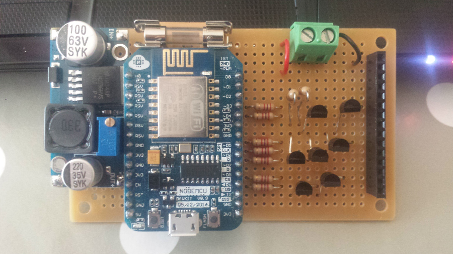
Firstly I don't believe the 3.3V terminals were ever intended to power the unit, they were intended for outputs to sensors etc. They may well accept an input but I'm not sure what the onboard voltage regulator will think about this. I would use the 5V pin for now.
Secondly the ESP only draws about 70mA at boot which is not a lot for your 3A buck converter. I've seen various reports of larger 5V power supplies not working well with the ESPs. It might be worth putting an external load in parallel with the nodeMCU to give the buck converter a bit of work to do at start up see if that helps. Whilst this is not a good long term solution it help you fault find.