Use this forum to chat about hardware specific topics for the ESP8266 (peripherals, memory, clocks, JTAG, programming)

User avatar
By rudy
#63759
btidey wrote:Original post says that external pull down didn't work. That sounds strange to me.

I find that pull ups are around 36K as measured on an ESP-12. An external pull down of 3.3K gives a default voltage of 0.27V before the sense of the pin is defined which is well below threshold turn on of any relay driver.

This is borne out by check measurements I took. I also checked with a scope and there were no unexpected transients.


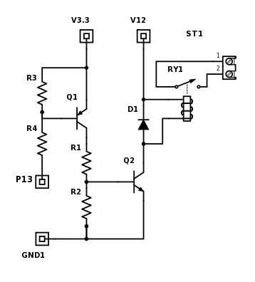
It all depends on the design of the relay driver. If it is a transistor with only a resistor in series with the base (no resistor to ground) then you could have the transistor turn on. If there was a low value resistance to ground then it should effectively short out the current from the pull ups. As I said, it depends on the way the relay driver was designed.
User avatar
By rudy
#63760
sean_intez wrote:
rudy wrote:That is perfectly acceptable as well. The point is to have two inverter stages. So that a high state (reset state) is also the off state for the relay.

I tend to use transistors because they were the cheapest switches for ages.

Image

R3 is optional as long as the internal pull up resistor is enabled at reset.

I will give this a try using a npn and pnp transistors. Thank you.
Do you have any suggestions on resistors value? my relay is also 3v3

edit:
in your suggestion, the relay state changes if the whole circuit loses power, right?


If there is no power then the Q1 has no power to turn on Q2. Q2's base will have a resistor to ground and that will keep it off. Even if there still is power for the relay it will not turn on since the base of the transistor is not getting any current from anywhere.
User avatar
By sean_intez
#63761
btidey wrote:Original post says that external pull down didn't work. That sounds strange to me.

I find that pull ups are around 36K as measured on an ESP-12. An external pull down of 3.3K gives a default voltage of 0.27V before the sense of the pin is defined which is well below threshold turn on of any relay driver.

This is borne out by check measurements I took. I also checked with a scope and there were no unexpected transients.

How did you measure internal resistors? did you just put your ohm meter between the pin and vcc pin while esp is not in circuit?

also how did you measure your relay driver threshold? I am using SEMICONDUCTOR MBT3904DW1T1G transistor array and here is my schematic
Image
User avatar
By rudy
#63762
Do you have any suggestions on resistors value? my relay is also 3v3


Just noticed this. Resistor values depend on the current requirements of the relay. I don't know the size of your relay so I'll just pick something as an example.

Say the relay needs 200mA. I was going to use the data for a 2N3904 but it isn't suited for that high a current. I typically would use a 2N4401 instead. I would use about 5mA of base current into it. I would make R1 390 Ohms and R2 1KOhms. For R3 and R4 I would use 10K for each. R3 and R2 are not that critical. Just as long as there is something there.