
- Wed Mar 15, 2017 3:49 pm
#63748
That is perfectly acceptable as well. The point is to have two inverter stages. So that a high state (reset state) is also the off state for the relay.
I tend to use transistors because they were the cheapest switches for ages.
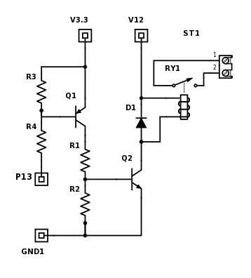
R3 is optional as long as the internal pull up resistor is enabled at reset.
I tend to use transistors because they were the cheapest switches for ages.
R3 is optional as long as the internal pull up resistor is enabled at reset.


