-->
Page 1 of 1

Can't set GPIO to OUTPUT

PostPosted: Mon Nov 23, 2015 1:46 am
by Toyman_R
I have rather funny situation: my complex scripts (e.g. temp reading and posting to MQTT server) work, but I can't make LED blink :-)
I am using a very basic script from IDE examples, but I can't get 3.3V (HIGH) voltage on the pin!
The same pin works OK as data pin for DHT22.
Module is ESP-12E, Arduino IDE 1.6.5
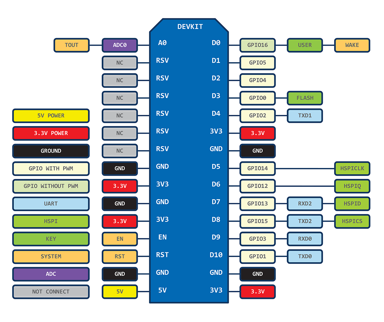
Re: Can't set GPIO to OUTPUT

PostPosted: Mon Nov 23, 2015 1:49 pm
by martinayotte
Are you doing a pinMode(pinno, OUTPUT) in your setup and than doing a digitalWrite(pinno, HIGH) ?
Please, share you small sketch to see where is the error ...

Re: Can't set GPIO to OUTPUT

PostPosted: Mon Nov 23, 2015 3:27 pm
by forlotto
set the pin low or as zero ...

I spent a lot of time trying to figure this out myself on the nodemcu.

After I set the pin as zero bingo it turned on which defies what I thought it would be logically represented as a 1 or on...

This is what has worked for me and what I continue to use it seems backwards but I also reflect this in my programming when showing the status as off or on.

I will warn this may be nodemcu specific and not the same for the esp as a standalone... but give it a try won't hurt.

Hope this helps.

PS would not hurt to share a bit more information on your hardware, setup, firmware etc...

As I stated this may be a nodemcu specific thing I have not used a module stand alone so your problem may lie else where but just give it a try set your pin low and be sure that you are programming for the correct pin and correct GPIO according to the firmware you are using check for pin map data. It is different between firmwares and IDE's....

Re: Can't set GPIO to OUTPUT

PostPosted: Thu Nov 26, 2015 12:58 pm
by bubba198
On module 12E the blue LED which is MOUNTED ON THE module itself it tied to GPIO 2 which is also the TX-only UART which spits out debug data when the ESP boots up. This is a UART with TX-only PIN and I read in the ESP spec sheet about it -- they warn people if they use that PIN as GPIO that during boot the user application will be disturbed due to the diag output stream.

To turn that LED ON in LUA I use:

Code: Select all> gpio.mode(4,gpio.OUTPUT)
> gpio.write(4,gpio.LOW)


Now if your module is part of an NodeMCU board then another LED exists on the board (not the module) and that one is tied to GPIO 0 and can be controlled with similar LUA commands just replace the GPIO number.

Now you noticed in LUA I said GPIO 2 but used gpio.mode(4,gpio.OUTPUT) to make it work -- same terrible mismatch as with Raspberry Pi etc -- the LUA wants physical PIN number on the ESP chip while the GPIO ports are't aligned with the physical PINs so one has to look at the picture to figure out which is which.

Hope that helps

Image