
- Sun Feb 07, 2016 2:04 pm
#40636
After toying around with esp's on breadboards, I thought it was time to start soldering one on my first PCB. I want to use a ESP-7 to read data from 2 ds18b20 sensors over HTTP.
I thought that by now I know the esp modules well enough to start soldering immediately, before booting it up for the first time. But now that I have everything in place, I seem to have a problem booting it up. I already found out that that the only way to get anything else than garbage out of it is by connecting to it using a unusual baud rate of 74886. When I do that I get:
ets Jan 8 2013,rst cause:2, boot mode:(3,6)
And nothing else, it does not respond to AT commands.
I've hooked the ESP-7 up in the following way:
GPIO15 --> GND
VCC --> 3.3V
GND--> GNG
EN --> 3.3V
TX --> RX on FTDI
RX --> TX on FTDI
GPIO4 --> Data pin of ds18b20
GPIO5 -->Data pin of ds18b20
Schematically it looks like this:
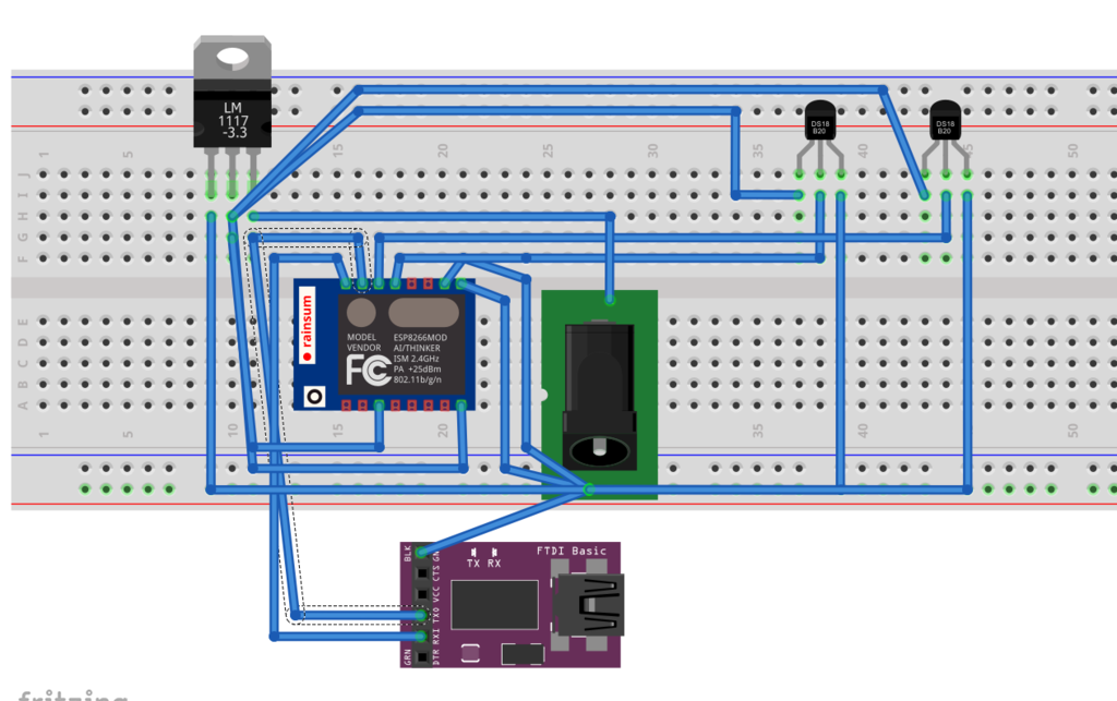
I have the feeling that the problem lies in the power supply to the module. I use a 9v adapter (That I have successfully worked with on ESP-1 and ESP-12 modules) and a LM1117 to convert the power to 3.3 volts. When I connect nothing to the output pin of the LM1117, I get around 3.3v out of it. As soon as I connect the ESP to it, the voltage drops to 1.8v (measurement between gnd and middel output pin), Wich to me doesn't sound good. I do however have no clue as to where I'm going wrong. Any ideas?
Last edited by ErikLem on Tue Feb 09, 2016 3:34 am, edited 1 time in total.


