
- Sun Jun 04, 2017 2:04 pm
#66718
I am a noob to be sure. I just spent days looking for the solution to my issue. I finally found it and would like to share. This I am sure is common knowledge to more experienced folks.
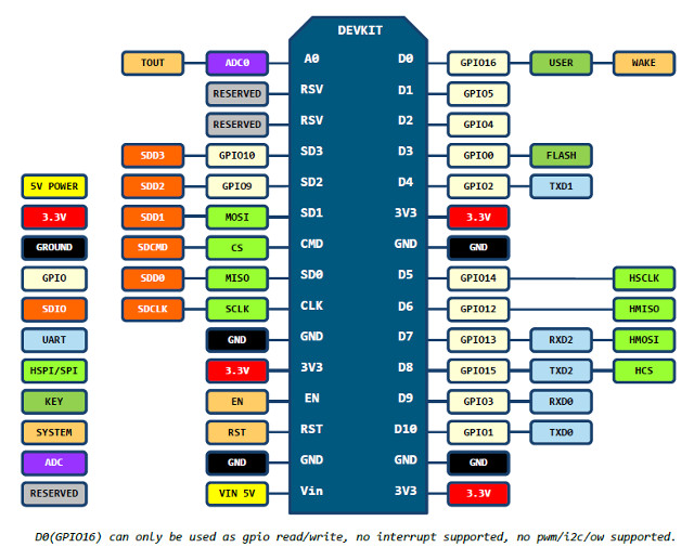
I am using an ESP8266MOD and a DHT22 sensor. I am using Arduino IDE 1.8.2 for an editor. To begin with I copied the simple DHT test sketch I think from Adafruit (thank you ladyada) and wired the sensor as prescribed to an Arduino ethernet as a test with the feedback wire connected to pin "4". Right off the bat I received good data back to the serial monitor. I then wired the same DHT22 sensor to my esp8266mod in the exact same manner connecting the feedback wire to pin "D4." I received the message "Failed to read from DHT sensor!" I spent a long time and worked through a lot of scenarios trying to figure this simple issue out. Then in post I found someone talking about "pin 2 on the arduino is not D2 on the 8266mod." So, my code reads "#define DHTPIN 4" but the wire is connected to D2 on the ESP8266 and I get exactly the data I expect in the serial monitor.
Now maybe someone could direct me to a good source of information to help me avoid these kinds of pitfalls with the esp8266 in the future, please? Also, it would be very nice if someone could explain why "DHTPIN 4" in Arduino IDE is D2 on the esp8266?
// Example testing sketch for various DHT humidity/temperature sensors
// Written by ladyada, public domain
#include <DHT.h>
#define DHTPIN 4 // what digital pin we're connected to
// Important to note that when wired to the esp8266mod
// even though pin "4" is specified data is on D2 of the 8266.
// Uncomment whatever type you're using!
//#define DHTTYPE DHT11 // DHT 11
#define DHTTYPE DHT22 // DHT 22 (AM2302), AM2321
//#define DHTTYPE DHT21 // DHT 21 (AM2301)
// Connect pin 1 (on the left) of the sensor to +5V
// NOTE: If using a board with 3.3V logic like an Arduino Due connect pin 1
// to 3.3V instead of 5V!
// Connect pin 2 of the sensor to whatever your DHTPIN is
// Connect pin 4 (on the right) of the sensor to GROUND
// Connect a 10K resistor from pin 2 (data) to pin 1 (power) of the sensor
// Initialize DHT sensor.
// Note that older versions of this library took an optional third parameter to
// tweak the timings for faster processors. This parameter is no longer needed
// as the current DHT reading algorithm adjusts itself to work on faster procs.
DHT dht(DHTPIN, DHTTYPE, 11);
void setup() {
Serial.begin(115200);
Serial.println("DHT22 Windows Machine test!");
dht.begin();
}
void loop() {
// Wait a few seconds between measurements.
delay(2000);
// Reading temperature or humidity takes about 250 milliseconds!
// Sensor readings may also be up to 2 seconds 'old' (its a very slow sensor)
float h = dht.readHumidity();
// Read temperature as Celsius (the default)
float t = dht.readTemperature();
// Read temperature as Fahrenheit (isFahrenheit = true)
float f = dht.readTemperature(true);
// Check if any reads failed and exit early (to try again).
if (isnan(h) || isnan(t) || isnan(f)) {
Serial.println("Failed to read from DHT sensor!");
return;
}
// Compute heat index in Fahrenheit (the default)
float hif = dht.computeHeatIndex(f, h);
// Compute heat index in Celsius (isFahreheit = false)
float hic = dht.computeHeatIndex(t, h, false);
Serial.print("Humidity: ");
Serial.print(h);
Serial.print(" %\t");
Serial.print("Temperature: ");
Serial.print(t);
Serial.print(" *C ");
Serial.print(f);
Serial.print(" *F\t");
Serial.print("Heat index: ");
Serial.print(hic);
Serial.print(" *C ");
Serial.print(hif);
Serial.println(" *F");
}


