So you're a Noob? Post your questions here until you graduate! Don't be shy.

User avatar
By Kowa92
#87978
pangolin wrote:I am really confused now - why have you got TWO esp-01 devices connected together? And why is c pulled to ground? That will force the ESP-01 into flash mode and not run the sketch.


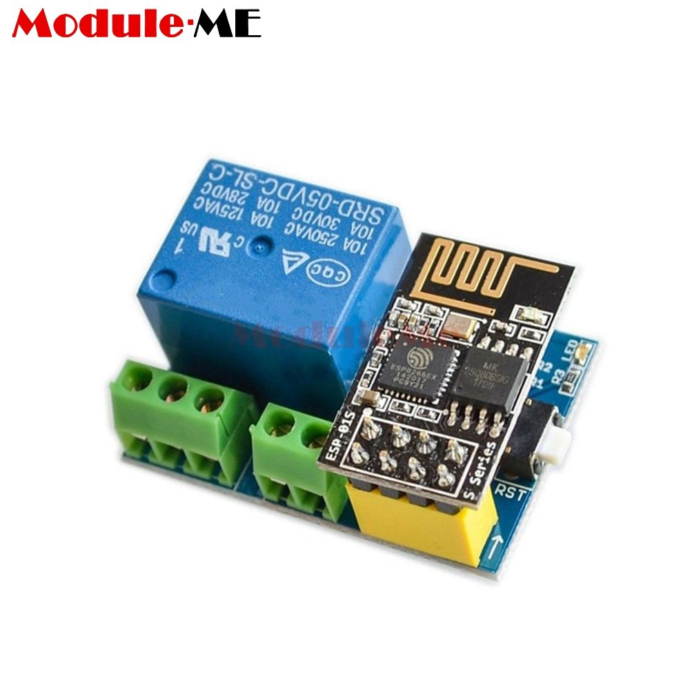
Nope i have 1 ESP8266 Relay v1.0 (left connector drew on left side of paper) and 1 ESP-01S (left connector drew on left right of paper). They are two different components.

Before i boot ESP-01S, i remove obviously GPIO0 from his actual connection (for avoid flash mode booting) and after i reconnect it to his terminal.
User avatar
By pangolin
#87985 "ESP8266 Relay v1.0 " sounds like it has an ESP8266 on it, or else the name means nothing. Why are you calling it that? if its just a relay then just call it a relay - if its an ESP8266 module with a relay attached , then you are connecting two ESP8266 together and so again, I ask why - what are you trying to acheive? WHat code is loaded into the "ESP8266 relay module" and what code is in the ESP-01 ?
User avatar
By prabbit237
#96401 I realize this is an old post but it never got a good answer and while the OP may have resolved his issue, others may have the same question.

The "ets Jan 8 2013, rst cause: 4, boot mode: (3,6)" is a watchdog reset but I didn't see anything in your code that enables the watchdog. But here's some thoughts:

The R2 on those v1.0 boards is a design flaw. Remove it and then the ESP-01 will boot properly and won't need to be disconnected and then connected after boot.

Next, try running the whole thing for quite some time without anything actually connected on the relay. Act as if there is by sending commands to turn it on, off, reboot the board, etc and see if you can force a glitch. If it's OK, then try driving a pure resistive load such as a halogen lamp of 500W or so. If still no glitches, then try a load again that has a motor (a fan or such.) If it now glitches, I'd look at a dirty power-supply, even if it seems good.

If you have the parts, hook the relay to a power-bank for the G/5V lines. Then try driving the load on the relay that was having issues and see if it glitches (the 5v will be totally removed from the A/C at this point, where-as a mains-powered 5v source is not totally isolated.) If it runs fine, then that shows there IS some spikes or brown-outs on the regular supply that's causing the issue.

And as a side note to pangolin, please research your answers. A search for ESP8266 Relay v1.0 board finds this: https://tasmota.github.io/docs/devices/ ... ngle-relay

Image

OP was putting the ESP-01 onto a separate breadboard and jumpering back to the 2x4 socket, possibly so he could avoid the "won't boot issue." As mentioned, removal of the R2 will stop that,