
- Wed Dec 24, 2014 10:02 pm
#5645
2017-02-07
This project has more posts and has been rebooted a while back too. There are now also video tutorials explaining everything from which components you need to how to solder, flash and program with the QuinLED board and the ESP-01. If you are interested in a small and easy to do project and have a WiFi controllable LED strips afterwards, this is for you!
Check out the index page with both the written tutorials and the video tutorials by clicking here.
I have started detailing on how to build this on my blog, next to reading this post please also read those pages. It explains how to do everything, what hardware you will need, etc.
Part 1: Setup, How it works
Part 2: Hardware and Tools needed to build it yourself and where to get it cheaply!
Part 3: Flashing and programming the ESP-01
Part 4: Configuring Domoticz
Part 5: Hacked Ikea LED lamps
Part 6: ESP8266 Domoticz Wall Switch
Part 7: Updated Dimmer and Domoticz code
Part 8: Version 2 of the PCB design
I've been looking at building my own network controlled LED driver/dimming module to run my LED strips in my home. The end result should be a module I hook up to LED strips and then control these over WiFi. I use Domoticz as a Domotica system.
A 'special' desire in this is that the lights must never instantly turn on or off but always fade between newly set values. The fading will have to be done in 'hardware', all other control is done using Domoticz. They offer a nice interface with sliders and the works.
After tinkering with an Arduino Nano coupled to a RM04 (Serial WiFi bridge) I have this working perfectly. I programmed both the Arduino and Domoticz side and my prototype has been working, without fail, for a few months now! I was about ready to get my custom PCB made for this and create the actual modules..... Then the ESP8266 came along!
The ESP8266 costs about $4 to $5 depending on desired pins, with an internal antenna! In contrast a Arduino Nano cost $4 and the RM04 cost around 10$ making the total $14! A serious cost saving can be realized here, IF I can get it working.
So after tinkering for 2 nights and overcomming some hurdles, the first part of it seems to work! I'm currently using the NodeLUA Build 20141222 firmware.
This works. The WiFi connection will be used in the future to provide input for the start and end values so it becomes network controllable, but for now it connects just fine.
The loop on the other hand seems a bit cluncky to me and it hangs up the whole ESP8266 while it's fading. WiFi even disconnects, but reconnects again after the loop is done. My Arduino version did not have this issue and I could even change the value while it was in a fade and it would instantly pick it up and start fading to the new value. Anybody have some tips for me on how to improve this?
When I have more time I will write more code and expand it to accept the values over a TCP connection and then process them, but since I'm not a coder, this is very much a work in progress.
--update
Ok, I've managed to clean up my code quite a bit and not make use of the tmr.wdclr() function any more. My new code uses the alarm timers and it's working like a charm. It takes a current value and a target value and then starts adding or subtracting values at a set rate thus changing the brightness of the LED. Using the timer I can even change the 'target' value while dimming and it will change towards the new value in real-time. Very awesome!
That means that even while a dimm/fade is running if I change the value it will automatically correct and end up at the right one!
The board also no longer hangs and keeps pinging back while doing the fade meaning that it can also accept an adjusted value if I hit the sliders in my Domotica system too much.
Now only to write a TCP incoming socket which then relays that number to the correct variable and also get this loop running permanently instead of having to call it each time!
--update
So, I've managed to write my first working version of this setup. Everything from the above listed dimming alarm timer, a listening TCP socket and an interpreting loop for LED1 (GPIO0) and LED2 (GPIO2) is in. They can be sent command's independently and don't seem to bother each other while working.
The way I send the commands to the module is using a program called "netcat". I run it on my Ubuntu Domoticz VMware guest. Those instructions look as following:
The LUA code I use on the ESP8266 is listed below. It's still a bit crude and currently dimming levels are set +1 or -1 per 30 microseconds. Although this is mathematically a smooth curve visually this is not and a logarithmic curve would be better. I don't know how to build that yet though and how it works now is good enough as a proof of concept and for me to go ahead. The module can now do everything my Arduino version could! Only exception is that the Arduino + RM04 costed me about 15$ and this module costs me 3.5$
I still have to re-write my Domoticz code and test this setup with the actual MOSFET's and strips connected and not some simple 2 pin LED's, but it should work the same. I will report back and also make some photo's of the setup!
--update 2014-12-31
I have been able to do a lot of work on my code today (The holidays help). I implemented a timed fader which automatically calculates the duration needed for the amount of steps to always make the fade last 5 seconds. So now a fade from 0 to 150 or from 0 to 1000 takes the same amount of time, the 0 to 1000 just runs the fade faster (It does not skip steps). This way you should have the most gradual fade at all times but also have a set value of how long it will take. The fade duration can be easily set in the code although in the future I might make it remotely configurable too.
I have also made progress and got everything working in Domoticz perfectly. The code I used for it though is kind of bad though (I wrote it a year ago when I didn't know LUA). I will update that code and then also post it.
Last but certainly not least, I've been able to write the first 2 parts of my guide on how to build this yourself! It now mainly describes how it works and what hardware I used to assemble it and where you can get it (for cheap)! I'm hoping it will help a lot of people looking for the same!
You can find my blog posts here (Setup) and here (Hardware)!
The newest v0.4 code you can find below. It works with both the firmware from the 22nd and the 30th.
--update 2015-01-02
I managed to make another 2 articles on my blog. This is the "How to flash and program your ESP-01" and "How to integrate with Domoticz" part! With that finished you can now create a dimmer which is fully controlled by a Domotica system!
--update 2015-01-03
Updated my Domoticz code (see blog post) to work with variables at the beginning of the screen and fix a bug where the LED would turn fully on when being turned off by a scene
Also made a video of the completed setup: http://youtu.be/r0mZF1C8Z-U?list=UU98qr ... 3Ne7zrbXvA
--update 2015-02-02
I soldered another board yesterday and it fully worked on both channels. That means now I have more working PCB's then not working PCB's, so I feel confident enough to share the design. It's a bit of a clunky design and v2 will be a lot better, but also more complex (using ESP-12). If you are going with my blog posts and the components listed there, this should work quite well.
A word of warning though, I give no guarantee this will work in your case and that the design of this board is perfect. It certainly is not and the way the voltage converter is connected with little wires is beyond clunky... It works though, no problem!
If you want to do me a favor, please buy it from here using the following link: http://dirtypcbs.com/view.php?share=3677&accesskey=68341995b44fe8081b778ea4761dae6a It will help me out a bit, and for you it just costs the normal very very low price of dirty PCB's anyway.
If you wish to get it somewhere else or modify it, You can download the fritzing file and gerber files here so you can use it yourself.
--update 2015-04-10
I have updated this post to include the new editions to my blog posts I have written. They include various parts using an ESP8266 in Domoticz. The most important one for the LED dimmer is Part 8, a new, much better and smaller, design for my LED dimmer board. It's now less then half as big and still includes all functions of the previous one. Anyone wanting to use these boards I recommend creating v2 from now on. You can read Part 8 here.
The applies to this one too, if you want to do me a favor, please buy the boards at DirtyPCB's using the following link. http://dirtypcbs.com/view.php?share=5691&accesskey=
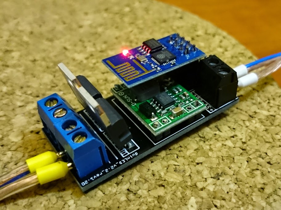
The new board!
 Viewed 20887 times")
 Viewed 20887 times")
This project has more posts and has been rebooted a while back too. There are now also video tutorials explaining everything from which components you need to how to solder, flash and program with the QuinLED board and the ESP-01. If you are interested in a small and easy to do project and have a WiFi controllable LED strips afterwards, this is for you!
Check out the index page with both the written tutorials and the video tutorials by clicking here.
I have started detailing on how to build this on my blog, next to reading this post please also read those pages. It explains how to do everything, what hardware you will need, etc.
Part 1: Setup, How it works
Part 2: Hardware and Tools needed to build it yourself and where to get it cheaply!
Part 3: Flashing and programming the ESP-01
Part 4: Configuring Domoticz
Part 5: Hacked Ikea LED lamps
Part 6: ESP8266 Domoticz Wall Switch
Part 7: Updated Dimmer and Domoticz code
Part 8: Version 2 of the PCB design
I've been looking at building my own network controlled LED driver/dimming module to run my LED strips in my home. The end result should be a module I hook up to LED strips and then control these over WiFi. I use Domoticz as a Domotica system.
A 'special' desire in this is that the lights must never instantly turn on or off but always fade between newly set values. The fading will have to be done in 'hardware', all other control is done using Domoticz. They offer a nice interface with sliders and the works.
After tinkering with an Arduino Nano coupled to a RM04 (Serial WiFi bridge) I have this working perfectly. I programmed both the Arduino and Domoticz side and my prototype has been working, without fail, for a few months now! I was about ready to get my custom PCB made for this and create the actual modules..... Then the ESP8266 came along!
The ESP8266 costs about $4 to $5 depending on desired pins, with an internal antenna! In contrast a Arduino Nano cost $4 and the RM04 cost around 10$ making the total $14! A serious cost saving can be realized here, IF I can get it working.
So after tinkering for 2 nights and overcomming some hurdles, the first part of it seems to work! I'm currently using the NodeLUA Build 20141222 firmware.
Code: Select all
-- Setup WiFi connection
wifi.setmode(wifi.STATION)
wifi.sta.config("SSID","PASSSSSS")

  print(wifi.sta.getip())

-- Setup initial value and enable LED pin(s)
pwm.setup(3, 400, 010)
pwm.start(3)

-- Loop for running LED's from PWM value 0 to PWM value 1000 in steps of 1 including a delay to slow down fade and using tmr.wdclr() to prevent the hardware watchdog killing the fade
for i = 0, 1000, 1 do
   pwm.setduty(3, i)
   tmr.delay(12500)
   tmr.wdclr()
end
This works. The WiFi connection will be used in the future to provide input for the start and end values so it becomes network controllable, but for now it connects just fine.
The loop on the other hand seems a bit cluncky to me and it hangs up the whole ESP8266 while it's fading. WiFi even disconnects, but reconnects again after the loop is done. My Arduino version did not have this issue and I could even change the value while it was in a fade and it would instantly pick it up and start fading to the new value. Anybody have some tips for me on how to improve this?
When I have more time I will write more code and expand it to accept the values over a TCP connection and then process them, but since I'm not a coder, this is very much a work in progress.
--update
Ok, I've managed to clean up my code quite a bit and not make use of the tmr.wdclr() function any more.
That means that even while a dimm/fade is running if I change the value it will automatically correct and end up at the right one!
The board also no longer hangs and keeps pinging back while doing the fade meaning that it can also accept an adjusted value if I hit the sliders in my Domotica system too much.
Now only to write a TCP incoming socket which then relays that number to the correct variable and also get this loop running permanently instead of having to call it each time!
Code: Select all
tmr.alarm(0, 21, 1, function()
 if current < target then
  current = (current + 1)
  print (current)
  pwm.setduty(3, current)
 elseif current > target then
  current = (current - 1)
  print (current)
  pwm.setduty(3, current)
 elseif current == target then tmr.stop(0)
end end )
--update
So, I've managed to write my first working version of this setup. Everything from the above listed dimming alarm timer, a listening TCP socket and an interpreting loop for LED1 (GPIO0) and LED2 (GPIO2) is in. They can be sent command's independently and don't seem to bother each other while working.
The way I send the commands to the module is using a program called "netcat". I run it on my Ubuntu Domoticz VMware guest. Those instructions look as following:
Code: Select all
quindor@domoticz:~$ echo LED2_target=999 | nc 10.10.200.10 43333
quindor@domoticz:~$ echo LED1_target=999 | nc 10.10.200.10 43333
quindor@domoticz:~$ echo LED1_target=005 | nc 10.10.200.10 43333
quindor@domoticz:~$ echo LED2_target=005 | nc 10.10.200.10 43333
The LUA code I use on the ESP8266 is listed below. It's still a bit crude and currently dimming levels are set +1 or -1 per 30 microseconds. Although this is mathematically a smooth curve visually this is not and a logarithmic curve would be better. I don't know how to build that yet though and how it works now is good enough as a proof of concept and for me to go ahead. The module can now do everything my Arduino version could! Only exception is that the Arduino + RM04 costed me about 15$ and this module costs me 3.5$
I still have to re-write my Domoticz code and test this setup with the actual MOSFET's and strips connected and not some simple 2 pin LED's, but it should work the same. I will report back and also make some photo's of the setup!
Code: Select all
pwm.setup(3, 1000, 005)
pwm.setup(4, 1000, 005)
pwm.start(3)
pwm.start(4)
LED1_current=005
LED1_target=005
LED2_current=005
LED2_target=005

wifi.setmode(wifi.STATION)
wifi.sta.config("SSID","PWPWPWPWPW")

print ("Booted to QuinLED_ESP8266_V0.2")

srv=net.createServer(net.TCP)
srv:listen(43333,function(conn)
    conn:on("receive",function(conn,payload)

    print("Input:"..payload)

    if string.find(payload,"LED1") then
        print("Received LED1 Target Value")
     LED1_target=tonumber(string.sub(payload, 13) )
    tmr.alarm(0, 30, 1, function()
     if LED1_current < LED1_target then
      LED1_current = (LED1_current + 1)
      pwm.setduty(3, LED1_current)
    elseif LED1_current > LED1_target then
      LED1_current = (LED1_current - 1)
      pwm.setduty(3, LED1_current)
    elseif LED1_current == LED1_target then tmr.stop(0)
     end end )
    end

    if string.find(payload,"LED2") then
        print("Received LED2 Target Value")
     LED2_target=tonumber(string.sub(payload, 13) )
    tmr.alarm(1, 30, 1, function()
     if LED2_current < LED2_target then
      LED2_current = (LED2_current + 1)
      pwm.setduty(4, LED2_current)
    elseif LED2_current > LED2_target then
      LED2_current = (LED2_current - 1)
      pwm.setduty(4, LED2_current)
    elseif LED2_current == LED2_target then tmr.stop(1)
     end end )
    end
    end)
    end)
--update 2014-12-31
I have been able to do a lot of work on my code today (The holidays help
I have also made progress and got everything working in Domoticz perfectly. The code I used for it though is kind of bad though (I wrote it a year ago when I didn't know LUA). I will update that code and then also post it.
Last but certainly not least, I've been able to write the first 2 parts of my guide on how to build this yourself! It now mainly describes how it works and what hardware I used to assemble it and where you can get it (for cheap)! I'm hoping it will help a lot of people looking for the same!
You can find my blog posts here (Setup) and here (Hardware)!
The newest v0.4 code you can find below. It works with both the firmware from the 22nd and the 30th.
Code: Select all
pwm.setup(3, 1000, 005)
pwm.setup(4, 1000, 005)
pwm.start(3)
pwm.start(4)

LED1_current=005
LED1_target=005
LED2_current=005
LED2_target=005

Fadetime1=5000
Fadetime2=5000

Stepcounter1=0
PosStepcounter1=0
DimTimer1=0

Stepcounter2=0
PosStepcounter2=0
DimTimer2=0

wifi.setmode(wifi.STATION)
wifi.sta.config("SSID","PASSSSS")


srv=net.createServer(net.TCP)
srv:listen(43333,function(conn)
    conn:on("receive",function(conn,payload)

    print("Input:"..payload)

    if string.find(payload,"LED1") then
     LED1_target=tonumber(string.sub(payload, 13) )
     print("Received LED1 Target Value: "..LED1_target)

     Stepcounter1=(LED1_target)-(LED1_current)

     if (Stepcounter1) < 0 then
      PosStepcounter1=(Stepcounter1)*-1
      else PosStepcounter1=(Stepcounter1)
     end

     if (PosStepcounter1) == 0 then
      PosStepcounter1=(PosStepcounter1)+1
      else PosStepcounter1=(PosStepcounter1)
     end

     DimTimer1=(Fadetime1)/(PosStepcounter1)

     if (DimTimer1) == 0 then
      DimTimer1=(DimTimer1)+1
      else DimTimer1=(DimTimer1)
     end

      print (Fadetime1)
      print (Stepcounter1)
      print (PosStepcounter1)
      print (DimTimer1)
      print (LED1_current)
      print (LED1_target)


    tmr.alarm(0, (DimTimer1), 1, function()
     if LED1_current < LED1_target then
      LED1_current = (LED1_current + 1)
      pwm.setduty(3, LED1_current)
    elseif LED1_current > LED1_target then
      LED1_current = (LED1_current - 1)
      pwm.setduty(3, LED1_current)
    elseif LED1_current == LED1_target then tmr.stop(0)
     end end )
    end

    if string.find(payload,"LED2") then
        print("Received LED2 Target Value")
     LED2_target=tonumber(string.sub(payload, 13) )

     Stepcounter2=(LED2_target)-(LED2_current)

     if (Stepcounter2) < 0 then
      PosStepcounter2=(Stepcounter2)*-1
      else PosStepcounter2=(Stepcounter2)
     end

     if (PosStepcounter2) == 0 then
      PosStepcounter2=(PosStepcounter2)+1
      else PosStepcounter2=(PosStepcounter2)
     end

     DimTimer2=(Fadetime2)/(PosStepcounter2)

     if (DimTimer2) == 0 then
      DimTimer2=(DimTimer2)+1
      else DimTimer2=(DimTimer2)
     end

      print (Fadetime2)
      print (Stepcounter2)
      print (PosStepcounter2)
      print (DimTimer2)
      print (LED2_current)
      print (LED2_target)


    tmr.alarm(1, (DimTimer2), 1, function()
     if LED2_current < LED2_target then
      LED2_current = (LED2_current + 1)
      pwm.setduty(4, LED2_current)
    elseif LED2_current > LED2_target then
      LED2_current = (LED2_current - 1)
      pwm.setduty(4, LED2_current)
    elseif LED2_current == LED2_target then tmr.stop(1)
     end end )
    end
    end)
    end)

print ("Booted to QuinLED_ESP8266_V0.4")
--update 2015-01-02
I managed to make another 2 articles on my blog. This is the "How to flash and program your ESP-01" and "How to integrate with Domoticz" part! With that finished you can now create a dimmer which is fully controlled by a Domotica system!
--update 2015-01-03
Updated my Domoticz code (see blog post) to work with variables at the beginning of the screen and fix a bug where the LED would turn fully on when being turned off by a scene
Also made a video of the completed setup: http://youtu.be/r0mZF1C8Z-U?list=UU98qr ... 3Ne7zrbXvA
--update 2015-02-02
I soldered another board yesterday and it fully worked on both channels. That means now I have more working PCB's then not working PCB's, so I feel confident enough to share the design. It's a bit of a clunky design and v2 will be a lot better, but also more complex (using ESP-12). If you are going with my blog posts and the components listed there, this should work quite well.
A word of warning though, I give no guarantee this will work in your case and that the design of this board is perfect. It certainly is not and the way the voltage converter is connected with little wires is beyond clunky... It works though, no problem!
If you want to do me a favor, please buy it from here using the following link: http://dirtypcbs.com/view.php?share=3677&accesskey=68341995b44fe8081b778ea4761dae6a It will help me out a bit, and for you it just costs the normal very very low price of dirty PCB's anyway.
If you wish to get it somewhere else or modify it, You can download the fritzing file and gerber files here so you can use it yourself.
--update 2015-04-10
I have updated this post to include the new editions to my blog posts I have written. They include various parts using an ESP8266 in Domoticz. The most important one for the LED dimmer is Part 8, a new, much better and smaller, design for my LED dimmer board. It's now less then half as big and still includes all functions of the previous one. Anyone wanting to use these boards I recommend creating v2 from now on. You can read Part 8 here.
The applies to this one too, if you want to do me a favor, please buy the boards at DirtyPCB's using the following link.
The new board!
Attachments
Last edited by Quindor on Tue Feb 07, 2017 4:48 pm, edited 15 times in total.


