- Mon Mar 28, 2016 2:11 pm
#44198
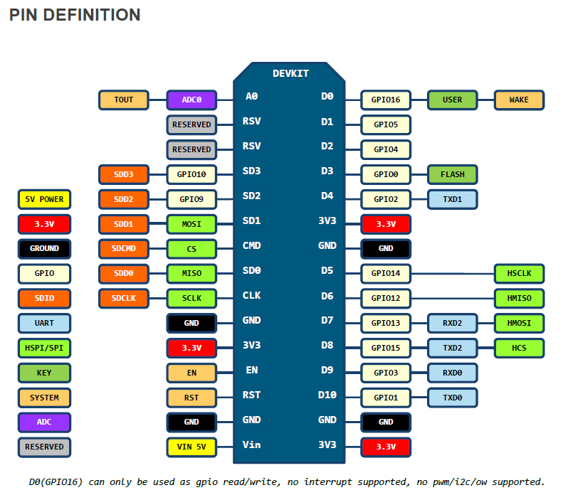
Solved but it needed a bit of soldering to free up GPIO9 and GPIO10 from the QIO flash programming.
The challenge is this is a tft display using SPI and a touch screen using SPI and a SD card slot using SPI. It needs 3 CS pins and a INT_REQ for the touchscreen. The nodemcu esp12E pins d0...d8 work but the project needs one more pin ...the cs pin for the card slot.
Each tft and touch work or tft and SD card work only all three of them need the extra cs pin
Code: Select all/// notes
/// the esp12e USES qio FOR THE PROGRAM FLASH
/// the places GOPI10 and GPIO9 as unavailable
/// unless the flash inside the can is removed and pins 3 and 7 lifted
/// pin 3 is wired to 7 and then to 3.3v
/// pads 3 and 7 are connected to GPIO9 and GPIO10
/// since GPIO9 and GPIO10 are now free and then set the FLASH to DIO mode
//// QIO will now not work
/// DIO mode maybe is the default for the arduino IDE NodeMCU v1 12E board
/// +--------+
/// _CS |1 8| 3.3v
/// DO |2 7| _HOLD
/// _WP |3 6| CLK
/// GND |4 5| DI
/// +--------+
#include <Arduino.h>
const int led = 2;
const int SD2 = 9;
const int SD3 = 10;
void setup()
{
//gpio_init();
Serial.begin(112500);
pinMode(SD2,FUNCTION_3); ////GPIO on 9 and 10 is function3
pinMode(SD3,FUNCTION_3); ////GPIO on 9 and 10 is function3
pinMode(led, OUTPUT);
pinMode(SD2, OUTPUT);
pinMode(SD3, OUTPUT);
delay(1000);
Serial.print("chipid");
Serial.println(ESP.getFlashChipId());
Serial.print("chipsize");
Serial.println(ESP.getFlashChipSize());
}
void loop() {
// put your main code here, to run repeatedly:
digitalWrite(led, 1);
digitalWrite(SD2, 1);
digitalWrite(SD3, 1);
delay(500);
digitalWrite(led, 0);
digitalWrite(SD2, 0);
digitalWrite(SD3, 0);
delay(500);
}
An alternative to soldering would be to use a MCP23S08 to get extra I/O....it looked messy since the arduino coders always try to make their code hardware independent. This results in very convoluted code in the low level routines that handle the hardware interface in this case SPI. The extra SPI transfers to enable the MCP23S08 would need to go into the SPI low level code but the code looked very very vulnerable to any additions.