- Tue Dec 29, 2015 8:43 pm
#37431
Thanks for the info.
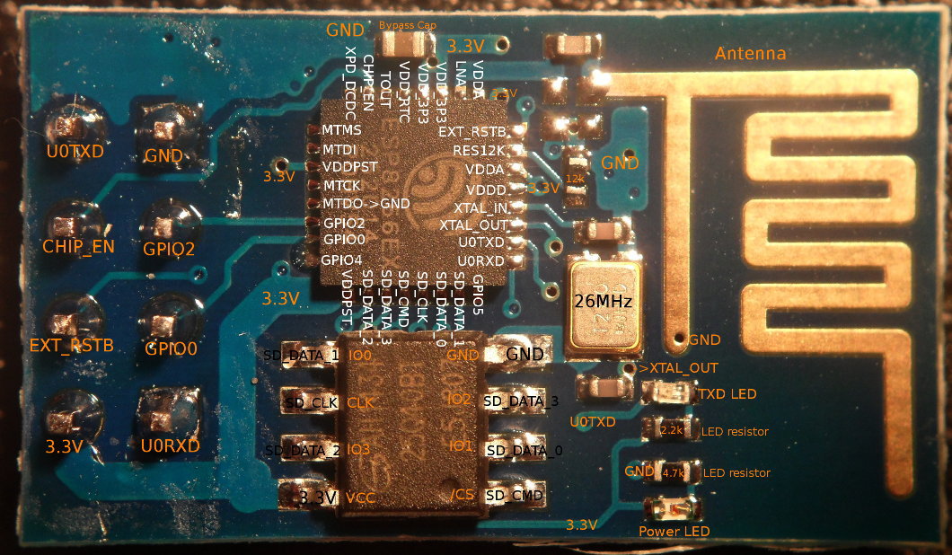
I guess i need to know the datasheet of the chip to know where to solder to extract the extra gpios for the connections:
1 CS --> IO2
2 DI(MOSI)-->IO13
3 VSS1--> GND
4 VDD-->3.3v
5 SCLK-->IO14
6 Vss2-->GND
7 DO(MISO)-->IO12
As for the GND And 3.3V, i can just connect that to my circuit as usual no? It doesnt have to pass trough the main chip, I suposse. (excuse me if the question is stupid, but I am a bit new to all this).
Thanks!