Your new topic does not fit any of the above??? Check first. Then post here. Thanks.

Moderator: igrr

User avatar
By mflmartin
#37481
martinayotte wrote:I would choose the common GND on perfboard option avoiding an additional tiny wire, which can bring noise on the power lines.
Enjoy your soldering challenge ! ;)


Thanks!

And about the soldering pins... is this correct?

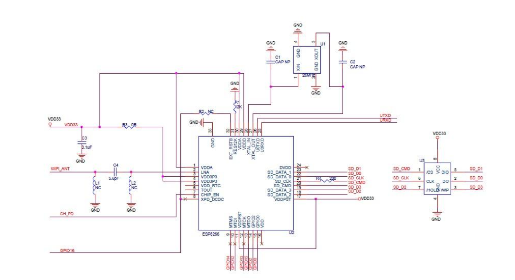
GPIO14, it is MTMS in your image, GPIO13 is MTCK and the GPIO12 is MTDI, no?

As found here:

https://nurdspace.nl/images/5/58/Esp8266_schema.png
User avatar
By treii28
#55286 Yeah i was looking this morning and there are some photos of people who have hardwired to the chip but I wouldn't want to have to try that - you'd need a really steady hand, good eyes, small wires and a lot of patience. I'm currently working on trying to find good ways to wire to an ESP-12 or ESP-07 directly without the dev board. Should be far easier.
User avatar
By Barnabybear
#55296
I'm currently working on trying to find good ways to wire to an ESP-12 or ESP-07 directly without the dev board. Should be far easier.

Hi, I'm not sure that 'good' is the term I'd use, but here's how I did my development untill a had some boards made. It was a upgrade to a project that had previously used ESP8266-01's. The card holder came from a £ shop.

https://dl.dropboxusercontent.com/u/763 ... %26_SD.jpg

Code: Select all The circuit:

 * SD card attached to SPI bus as follows:
 ** MOSI (2) - GPIO 11
 ** MISO (7) - GPIO 12 // 10K pull up
 ** CLK (5) - GPIO 13
 ** CS (1) - GPIO 15 // changed from GPIO 4.
// Actual terminals on card socket from the cut corner
// 9, 1, 2, 3, 3, 4, 5, 6, 7, 8 for SD

I started with this sketch.
https://www.arduino.cc/en/Tutorial/DumpFile