Place to put your Basic demos and examples

Moderator: Mmiscool

User avatar
By forlotto
#46629 Upon further investigation I discovered a slight issue with dimming using this circuit and my code.

Problem: There is a flicker that is variable no matter what light source used below full on.

Solutions: I am currently searching for a solution.

I have tried a bypass module and a 1.5k 25watt wire wound resistor figuring that there needed to be extra power to keep things going. They have not worked.

Some other things to try that I have not.

Adding a capacitor to the VCC and GND pins 0.1uf 3.3v and GND and possibly adding a cap to the 5v vcc in dunno the value needed for that one as of yet.

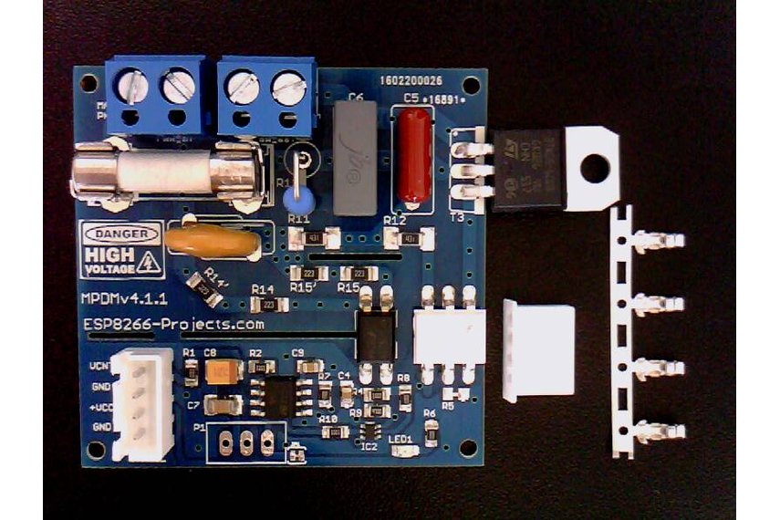
The seller has also discontinued sales it appears of his circuit thewp122 no longer seems to carry his hardware in stock so I have located a source of a similar PCB priced pretty aggressively as well in comparison. So rather than working up on a chair on the device streatching to reach my 10ft ceiling I will likely be ordering another board so I can do some testing down low.

MMiscool I sent you one of these boards if you could do some testing and help me figure out a remedy to the flicker problem this would be sweet I know you are way busy with dev work and the maker space etc so you likely will not have time for something like this but I would love to get it working without the need for an external DAC over the I2C bus. Simple is Basic so Basic should be simple even on the hardware side that is the goal for me.


Oh the source if interested is https://www.tindie.com/products/nEXT_EV ... r-mpdmv41/

This will be the new board being used in the future as time provides.

Need to figure out the flicker problem to enable full smooth function of our community based espbasic dimmer.

I have also contacted the developer of the dimmer module and asked for him to possibly chime in and help us out as well with his hardware to get this thing functional and flicker free limitations or not.

@nextevo AKA trackerj
if you are out there join us! Lets make this thing work well no extra hardware I know it is possible!
Last edited by forlotto on Sun May 01, 2016 4:27 pm, edited 1 time in total.
User avatar
By trackerj
#46633 Hello All ,

First of all I want to Thank you for the invitation on your ESP Basic Forum.

Hi forlotto, now about your question:

I have no experience at all with espbasic coding and available functions but as long as you can provide a proper VCNT signal (Voltage control) to the MPDMv4 Board (by PWM or DAC or whatever other digital-to-analog function you might have available in the espbasic) it should work OK.

You don't need to do in software any kind of Phase detection/ZDC at all. This is the whole point of the MPDMv4 board, to make it deadly simple to be used. And MCU overhead free.

If you take a look at the MPDMv4 Board description and the Youtube video from below, you will see how simple is to drive it:


I don't know if this is appropriate to post here, as is not BASIC code, but please see below, just to give you a better idea, a very simple example of how to drive it using Arduino IDE :

Code: Select allint VCNT = 3;    // MPDMv4 Voltage Control Pin (VCNT) connected to Arduino PIN3

void setup()
{
  // initialize the serial communication:
  Serial.begin(9600);
  // initialize the VCNT pin as an output:
  pinMode(VCNT, OUTPUT);
}

void loop() {
  byte brightness;

  // check if data has been sent from the computer:
  if (Serial.available()) {
    // read the most recent byte -> range from 0 to 190 : MPDMv4 Calibrated range
    brightness = Serial.parseInt();
    Serial.print("Command received : ");
    Serial.println(brightness);   
    // set the brightness -> range from 0 to 190 : MPDMv4 Calibrated range

    analogWrite(VCNT, brightness);
  }
}


and that's it, simple as that!

Regarding hardware, you need a decent PSU, properly filtered. And of course, if you use PWM as in the above example you need a decent smoothing RC filter on the VCNT signal. I still recommend a DAC for generating the VCNT signal (deadly cheap this days) or a MCU with hardware PWM but if you have in espbasic a good software PWM function should work ok.
What I don't like in general about software PWM is the fact that is using MCU resources and is less precise than the hardware one. And also is deviating a bit from the "MCU overhead free" idea.

For any other questions, please feel free to contact me anytime, here or my blog.
User avatar
By forlotto
#46644 @trackerj aka nextevo (I believe?)

Basic is built of of the work of the arduino code by IGRR for the esp it was totally appropriate to share this info. Basic makes it easier to preform said operations with a lot less code and efficient use of resources. Also the interface makes it easy for connections to wifi etc.

I have placed an order for two units on tindie and am awaiting their arrival I assume it will likely take a couple of weeks for the products to reach me here in the United States.

Can't wait to give them a try I would like to see you stick with Dupont based 4pin header instead of this header that I am not familiar with looks like possibly JST or something... Would it be possible to include the header with some wire pigtail that I can splice into so I do not have to source the parts to make the proper connections?

I may be able to widen the through hole a bit and switch out the header providing it does not require me to drill too wide as to remove the entire trace. But for now I will start with trying your hardware implementation to see how well it functions and if I will need to smooth things out via the input output.

What do you suggest to use to smooth out the input and ouput?
A list of parts and where to connect them would be great so I can be sure any flicker issues I run into will not be happening due to my modified wall plug power supply, or the circuitry on my nodemcu.

I look forward to getting this hardware and giving it an honest test any help would be greatly appreciated trackerj!

I really suggest you try out basic a little we all welcome you trust me on this one this is a great project full of great folks coming up with interesting projects and solutions for stuff and making it a reality for anyone to provide easy controls for all kinds of devices.

Enjoy and I cannot wait to see you jump in with us on espbasic and possibly share your projects in basic format for the basic community it is a lot easier to preform many operations in basic and the development times are therefore improved by requiring less code to preform a task.

To turn the LED on on a nodemcu with basic here is an example:
Code: Select allpo d4 0

To turn the LED off
Code: Select allpo d4 1

To do pwm on d4 pin
Code: Select allpwo d4 190


If you are using just the esp8266 rather than a nodemcu it will be:
Code: Select allpo 2 0
po 2 1
pwo 2 190


Here is the pinout code that designates the pins for nodemcu:
  if (PinDesignaor == "D0")  pin = 16;
  if (PinDesignaor == "D1")  pin = 5;
  if (PinDesignaor == "D2")  pin = 4;
  if (PinDesignaor == "D3")  pin = 0;
  if (PinDesignaor == "D4")  pin = 2;
  if (PinDesignaor == "D5")  pin = 14;
  if (PinDesignaor == "D6")  pin = 12;
  if (PinDesignaor == "D7")  pin = 13;
  if (PinDesignaor == "D8")  pin = 15;
  if (PinDesignaor == "RX")  pin = 3;
  if (PinDesignaor == "TX")  pin = 1;


If you would like to study some example code and such check out the link in my signature it will show you somethings that will give you an idea about basic!

really simple! I think you might benefit from the simplicity as well.

Basic is all done from the web browser so once it is programmed you just point your browser to the device ip and you can update your code from the browser based editor!

It makes life a lot easier give it a try trackerj I'm sure you will see the benefit as the rest of us do!
User avatar
By trackerj
#46660 Hi Forlotto,

yes, joined the club :)

Have seen your order, will be sent tomorrow. From previous experience it will take about 2 weeks or so with regular Post.

Regarding the connector: is has the standard 2.54mm spacing, so if you don't like it, you can easy replace it with whatever header you might want. Also, in the future, I have no problem to change it or even send it without any soldered connector/header so anybody cand use it's own desired one. As I said, spacing is standard, Dupont based 4pin header friendly :)

The MPDMv4 delivery Kit is containing also the pins&header for them, you don't need to buy anything else, look at the picture on Tindie, same as below:

Image

Will try today to upload the BASIC stuff on one of the ESP8266 boards and will give it a try :)

Will post later the results. I don't have a nodemcu board around but I cannot see any reason to not work on my nEXT EVO Board.

Regarding smoothing out the input and ouput, If I understand well your question, you need a proper decent filtered PSU for 3.3V power, and maybe an additional RC filter if using PWM for VCNT signal. On the AC MAINS side, as been a Triac controlled unit, I will suggest the usual snubber + EMI filter. This is more for by the book EMI compliance than a direct functional request. A standard snubber circuit is already in place onboard :)

See ya later,
TJ.