Post links and attach files for documentation here, also chat about these docs freely

User avatar
By w11
#30859
mohsenabutalebi wrote:I have tested ADC.when I apply voltages more than 9.6 v it read 1024. so I think voltage reference of it's ADC is 9.6v .Any body did the same?


Woohoo. Thats more than Espressif wrote in their datasheets.
Have a look here: http://bbs.espressif.com/viewtopic.php? ... 1545#p1545
All digital IO pins are protected from over-voltage with a snap-back circuit connected between the
pad and ground. The snap back voltage is typically about 6V, and the holding voltage is 5.8V. This
provides protection from over-voltages and ESD. The output devices are also protected from
reversed voltages with diodes.
found in "0B-ESP8266__Hardware_User_Guide__EN_v1.1.pdf"

Also there a topic about 3.9. ADC (Analog-to-digital Converter)
ESP8266EX is embedded with a 10-bit precision SARADC. Currently, TOUT (Pin6) is defined as ADC
interface..

The input voltage range is 0 to 1.0 V when TOUT is connected to external circuit.
User avatar
By eriksl
#31396
mohsenabutalebi wrote:I have tested ADC.when I apply voltages more than 9.6 v it read 1024. so I think voltage reference of it's ADC is 9.6v .Any body did the same?

I assume you mean 0.96V, not 9.6V. It can very well the case. It's probably a multiple of some diode's bandgap voltage. It's very hard to make it exactly 1.0V.
User avatar
By EspFan
#31567 I'm pretty sure you don't want to apply 9v to any pin unless you want to fry it.

Did you slowly ramp up the voltage using a high accuracy power source to come to that number? Can you please explain how you arrived at 9.6v.
User avatar
By trackerj
#31572 As maximum voltage input is expected to be 1V only and because your desired input Voltage is 5V it's obviously that we need to find a way to "translate" the voltage domain between 0-5V to 0-1V.

They are many different techniques available for doing that but the easiest one to useis the Resistive Voltage Divider (RVD). Very crude but effective, with the right quality and precision resistors.

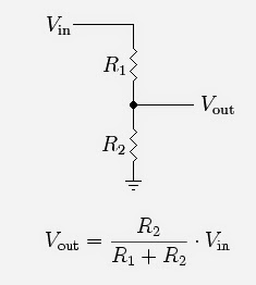
A RVD (also known as a potential divider) is a passive linear circuit that produces an output voltage (Vout) that is a fraction of its input voltage (Vin). Voltage division is the result of distributing the input voltage among the components of the divider.

Image

Let's find out what resistor values we will need for our RVD:

Vinmax = 5V
Voutmax = VADCin_max = 1V
Vout=Vin*R2/(R1+R2)

From the resistor ratio calculation values are: R1=40K and R2=10k. You can choose also other values as long as you keep accurate the ratio between, better go upper that that. 400k and 100k should give the same result for example but be careful with the input impedance! As a general practice a Op Amp Buffer will be a good add-on.

Related article : ESP8266 Internal ADC Explained

And an example of a buffered input ADC input Voltage Level Shifter and amplifier module