
- Sun Sep 25, 2016 1:53 pm
#55685
Hello everyone
For a while now, I am trying to setup my first ESP8266 project, however I have no luck and I ended destroying 5 units so far.
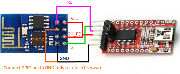
What I am trying to do is flash ESP8266-1 with NodeMCU firmware and upload a program with ESPlorer as described in the following tutorial via an FTDI chip. I've tried both powering the ESP directly from the FTDI chip (3.3V) or via an external power supply.
http://randomnerdtutorials.com/esp8266-web-server/
After flashing the NodeMCU and unplugging the GPIO2 from the ground the ESP acts strange like it has a short curcuit. The red led starts to flicker or dim out and the unit starts to heat up after a while. At first I manage to upload the code and in my last attempt I even got a respond when trying to access the server via my pc browser. However, not long after powering the unit, ESP stops responding neither it connects to my modem or can communicate with it via the FTDI chip.
As I already told you, I think all of my units have been destroyed due to the temperature build up, however I am not entirely sure. The units I used are cheap ebay ones, so maybe those are poorly made. What really troubles me is that I don't have those issues just before flashing the NodeMCU firmware.
Any ideas on what I am supposed to do? anyone else experienced some problem? Am I doing something wrong? Just to note the units I used are black and not blue as the most pictures I manage to find on the net. Does it worth buying a ESP from a local ventor or I will just through more money?
For a while now, I am trying to setup my first ESP8266 project, however I have no luck and I ended destroying 5 units so far.
What I am trying to do is flash ESP8266-1 with NodeMCU firmware and upload a program with ESPlorer as described in the following tutorial via an FTDI chip. I've tried both powering the ESP directly from the FTDI chip (3.3V) or via an external power supply.
http://randomnerdtutorials.com/esp8266-web-server/
After flashing the NodeMCU and unplugging the GPIO2 from the ground the ESP acts strange like it has a short curcuit. The red led starts to flicker or dim out and the unit starts to heat up after a while. At first I manage to upload the code and in my last attempt I even got a respond when trying to access the server via my pc browser. However, not long after powering the unit, ESP stops responding neither it connects to my modem or can communicate with it via the FTDI chip.
As I already told you, I think all of my units have been destroyed due to the temperature build up, however I am not entirely sure. The units I used are cheap ebay ones, so maybe those are poorly made. What really troubles me is that I don't have those issues just before flashing the NodeMCU firmware.
Any ideas on what I am supposed to do? anyone else experienced some problem? Am I doing something wrong? Just to note the units I used are black and not blue as the most pictures I manage to find on the net. Does it worth buying a ESP from a local ventor or I will just through more money?


