
- Sat May 21, 2016 10:01 pm
#47789
So did you have to Flash the shield with the AT firmware as described in the thread. I have a ESP13 wifi shield and A UNO and I have the same problem with the one serial port. The two DIP on off position I can upload a sketch turning them to ON shuts down the serial port I can't see what the esp is sending back. Softserial is the answer but I am not sure how to wire that up. Do you have the DIP switch off, then wire the pins 6,7 or 2,3 as software serial to the ESP.
- Sun May 22, 2016 7:44 am
#47806
No, I didn't reflash anything. In fact, I've not been able to communicate with the board; the one utility I found is in Chinese, so pretty much unusable without a lot of guessing. Thats still something I need to sort out, as the baud rate is at 115200, and soft serial struggles at that rate, need to bring it down to 9600.
My shield (same style as mentioned earlier in this thread) has 4 DIP switches. 3 and 4 appear to be for putting it in firmware upgrade mode, the other two are "off" or down.
When you look at the typical sketch using software serial, you'll notice it will reference two pin numbers:
#include "SoftwareSerial.h"
SoftwareSerial Serial1(2, 3); // RX, TX
Those are the rx/tx pin numbers for the software serial port. They can be any digital pins you chose, except, of course, 0 and 1, which are the hardware serial port pins. I ran jumpers from those two pins to the rx/tx pins for the 8266 module that is on the board. It does not appear, as best I can see, that the rx/tx pins for the 8266 are brought out to the shield headers, so you HAVE to make the rx/tx connection yourself. That was the "aha" moment for me with this shield and how it was designed. When you think about it, that gives you more flexibility, you just need to be aware thats how it is set up.
You'll also need to set speed for both the software serial ports, one for your debug serial port, one to match whatever your 8266 shield is set for:
// initialize serial for debugging
Serial.begin(115200);
// initialize serial for ESP module
Serial1.begin(115200);
// initialize ESP module
WiFi.init(&Serial1);
Its likely your shield is set for either 9600 or 115200. The software serial seems to struggle at 115200, but I haven't spent anymore time with the shield and the process to lower the speed. I know what I need to do, just haven't spent the time to sort out how I need to access and flash the 8266 module.
Listed below is the example sketch I used to have it attach to my home wifi and give me rssi readings:
/*
WiFiEsp example: ConnectWPA
This example connects to an encrypted WiFi network using an ESP8266 module.
Then it prints the MAC address of the WiFi shield, the IP address obtained
and other network details.
For more details see: http://yaab-arduino.blogspot.com/p/wifi ... nnect.html
*/
#include "WiFiEsp.h"
// Emulate Serial1 on pins 6/7 if not present
#ifndef HAVE_HWSERIAL1
#include "SoftwareSerial.h"
SoftwareSerial Serial1(2, 3); // RX, TX
#endif
char ssid[] = "YOUR SSID"; // your network SSID (name)
char pass[] = "YOUR PASSWORD"; // your network password
int status = WL_IDLE_STATUS; // the Wifi radio's status
void setup()
{
// initialize serial for debugging
Serial.begin(115200);
// initialize serial for ESP module
Serial1.begin(115200);
// initialize ESP module
WiFi.init(&Serial1);
// check for the presence of the shield
if (WiFi.status() == WL_NO_SHIELD) {
Serial.println("WiFi shield not present");
// don't continue
while (true);
}
// attempt to connect to WiFi network
while ( status != WL_CONNECTED) {
Serial.print("Attempting to connect to WPA SSID: ");
Serial.println(ssid);
// Connect to WPA/WPA2 network
status = WiFi.begin(ssid, pass);
}
Serial.println("You're connected to the network");
}
void loop()
{
// print the network connection information every 10 seconds
Serial.println();
printCurrentNet();
printWifiData();
delay(10000);
}
void printWifiData()
{
// print your WiFi shield's IP address
IPAddress ip = WiFi.localIP();
Serial.print("IP Address: ");
Serial.println(ip);
// print your MAC address
byte mac[6];
WiFi.macAddress(mac);
char buf[20];
sprintf(buf, "%02X:%02X:%02X:%02X:%02X:%02X", mac[5], mac[4], mac[3], mac[2], mac[1], mac[0]);
Serial.print("MAC address: ");
Serial.println(buf);
}
void printCurrentNet()
{
// print the SSID of the network you're attached to
Serial.print("SSID: ");
Serial.println(WiFi.SSID());
// print the MAC address of the router you're attached to
byte bssid[6];
WiFi.BSSID(bssid);
char buf[20];
sprintf(buf, "%02X:%02X:%02X:%02X:%02X:%02X", bssid[5], bssid[4], bssid[3], bssid[2], bssid[1], bssid[0]);
Serial.print("BSSID: ");
Serial.println(buf);
// print the received signal strength
long rssi = WiFi.RSSI();
Serial.print("Signal strength (RSSI): ");
Serial.println(rssi);
}
Good luck, hope this helps!
Frank Spina wrote:So did you have to Flash the shield with the AT firmware as described in the thread.
I have a ESP13 wifi shield and A UNO and I have the same problem with the one serial port. The two DIP on off position I can upload a sketch turning them to ON shuts down the serial port I can't see what the esp is sending back. Softserial is the answer but I am not sure how to wire that up. Do you have the DIP switch off, then wire the pins 6,7 or 2,3 as software serial to the ESP.
No, I didn't reflash anything. In fact, I've not been able to communicate with the board; the one utility I found is in Chinese, so pretty much unusable without a lot of guessing. Thats still something I need to sort out, as the baud rate is at 115200, and soft serial struggles at that rate, need to bring it down to 9600.
My shield (same style as mentioned earlier in this thread) has 4 DIP switches. 3 and 4 appear to be for putting it in firmware upgrade mode, the other two are "off" or down.
When you look at the typical sketch using software serial, you'll notice it will reference two pin numbers:
#include "SoftwareSerial.h"
SoftwareSerial Serial1(2, 3); // RX, TX
Those are the rx/tx pin numbers for the software serial port. They can be any digital pins you chose, except, of course, 0 and 1, which are the hardware serial port pins. I ran jumpers from those two pins to the rx/tx pins for the 8266 module that is on the board. It does not appear, as best I can see, that the rx/tx pins for the 8266 are brought out to the shield headers, so you HAVE to make the rx/tx connection yourself. That was the "aha" moment for me with this shield and how it was designed. When you think about it, that gives you more flexibility, you just need to be aware thats how it is set up.
You'll also need to set speed for both the software serial ports, one for your debug serial port, one to match whatever your 8266 shield is set for:
// initialize serial for debugging
Serial.begin(115200);
// initialize serial for ESP module
Serial1.begin(115200);
// initialize ESP module
WiFi.init(&Serial1);
Its likely your shield is set for either 9600 or 115200. The software serial seems to struggle at 115200, but I haven't spent anymore time with the shield and the process to lower the speed. I know what I need to do, just haven't spent the time to sort out how I need to access and flash the 8266 module.
Listed below is the example sketch I used to have it attach to my home wifi and give me rssi readings:
/*
WiFiEsp example: ConnectWPA
This example connects to an encrypted WiFi network using an ESP8266 module.
Then it prints the MAC address of the WiFi shield, the IP address obtained
and other network details.
For more details see: http://yaab-arduino.blogspot.com/p/wifi ... nnect.html
*/
#include "WiFiEsp.h"
// Emulate Serial1 on pins 6/7 if not present
#ifndef HAVE_HWSERIAL1
#include "SoftwareSerial.h"
SoftwareSerial Serial1(2, 3); // RX, TX
#endif
char ssid[] = "YOUR SSID"; // your network SSID (name)
char pass[] = "YOUR PASSWORD"; // your network password
int status = WL_IDLE_STATUS; // the Wifi radio's status
void setup()
{
// initialize serial for debugging
Serial.begin(115200);
// initialize serial for ESP module
Serial1.begin(115200);
// initialize ESP module
WiFi.init(&Serial1);
// check for the presence of the shield
if (WiFi.status() == WL_NO_SHIELD) {
Serial.println("WiFi shield not present");
// don't continue
while (true);
}
// attempt to connect to WiFi network
while ( status != WL_CONNECTED) {
Serial.print("Attempting to connect to WPA SSID: ");
Serial.println(ssid);
// Connect to WPA/WPA2 network
status = WiFi.begin(ssid, pass);
}
Serial.println("You're connected to the network");
}
void loop()
{
// print the network connection information every 10 seconds
Serial.println();
printCurrentNet();
printWifiData();
delay(10000);
}
void printWifiData()
{
// print your WiFi shield's IP address
IPAddress ip = WiFi.localIP();
Serial.print("IP Address: ");
Serial.println(ip);
// print your MAC address
byte mac[6];
WiFi.macAddress(mac);
char buf[20];
sprintf(buf, "%02X:%02X:%02X:%02X:%02X:%02X", mac[5], mac[4], mac[3], mac[2], mac[1], mac[0]);
Serial.print("MAC address: ");
Serial.println(buf);
}
void printCurrentNet()
{
// print the SSID of the network you're attached to
Serial.print("SSID: ");
Serial.println(WiFi.SSID());
// print the MAC address of the router you're attached to
byte bssid[6];
WiFi.BSSID(bssid);
char buf[20];
sprintf(buf, "%02X:%02X:%02X:%02X:%02X:%02X", bssid[5], bssid[4], bssid[3], bssid[2], bssid[1], bssid[0]);
Serial.print("BSSID: ");
Serial.println(buf);
// print the received signal strength
long rssi = WiFi.RSSI();
Serial.print("Signal strength (RSSI): ");
Serial.println(rssi);
}
Good luck, hope this helps!
- Sun May 22, 2016 11:00 am
#47824
" It does not appear, as best I can see, that the rx/tx pins for the 8266 are brought out to the shield headers, so you HAVE to make the rx/tx connection yourself. That was the "aha" moment for me with this shield and how it was designed. When you think about it, that gives you more flexibility, you just need to be aware thats how it is set up. "
My headers labeled TX0 and RX0 look like they are connected. So I just put some jumper wires for TX to Pin 2, RX to PIN 3, based on your code. I get a timeout when the ESP was initialized. I have tried both 9600 and 115200.
One other thing what is your dip set to. I only get the time out int he serial output when I set the dip to OFF. When I turn them on I get garbage, probably because it turns off the serial output.
- Sun May 22, 2016 11:21 am
#47826
All 4 dip switches on mine are off.
As far as rx/tx connections, there is a 5 pin debug port that I connected to. The board looks like this one: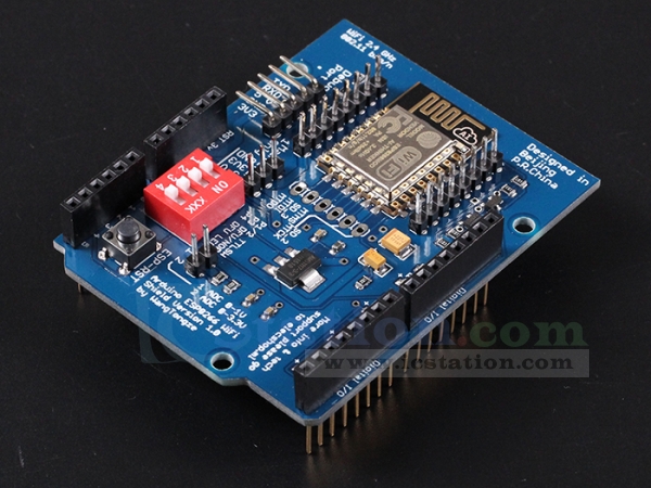
Frank Spina wrote:" It does not appear, as best I can see, that the rx/tx pins for the 8266 are brought out to the shield headers, so you HAVE to make the rx/tx connection yourself. That was the "aha" moment for me with this shield and how it was designed. When you think about it, that gives you more flexibility, you just need to be aware thats how it is set up. "
My headers labeled TX0 and RX0 look like they are connected. So I just put some jumper wires for TX to Pin 2, RX to PIN 3, based on your code. I get a timeout when the ESP was initialized. I have tried both 9600 and 115200.
One other thing what is your dip set to. I only get the time out int he serial output when I set the dip to OFF. When I turn them on I get garbage, probably because it turns off the serial output.
All 4 dip switches on mine are off.
As far as rx/tx connections, there is a 5 pin debug port that I connected to. The board looks like this one:


