- Wed Aug 31, 2016 8:17 am
#54169
Hi, and nice job.
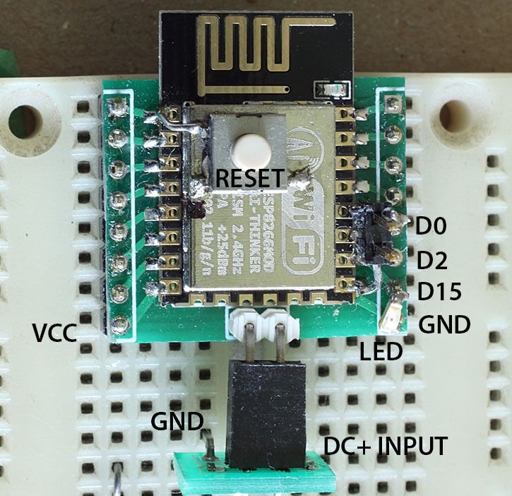
I had used the cheap breakout boards for the ESP-12 and they certainly are not breadboard friendly. I had some extra space on a PCB at work so I made a somewhat better layout. It at least exposes a set of pins on each side of the board.
But what I wanted to mention is that I also solder a 0.1" header pins to the top of the module so I can put it into programming mode. It is in the picture but hard to make out, a side view would be more clear. I also solder a small switch to the metal shield (ground) and reset. So that I can easily reset the board. And on D15, along with the required pull down resistor I solder a surface mount LED and resistor as another status indicator.
And I might as well show the back of the board.
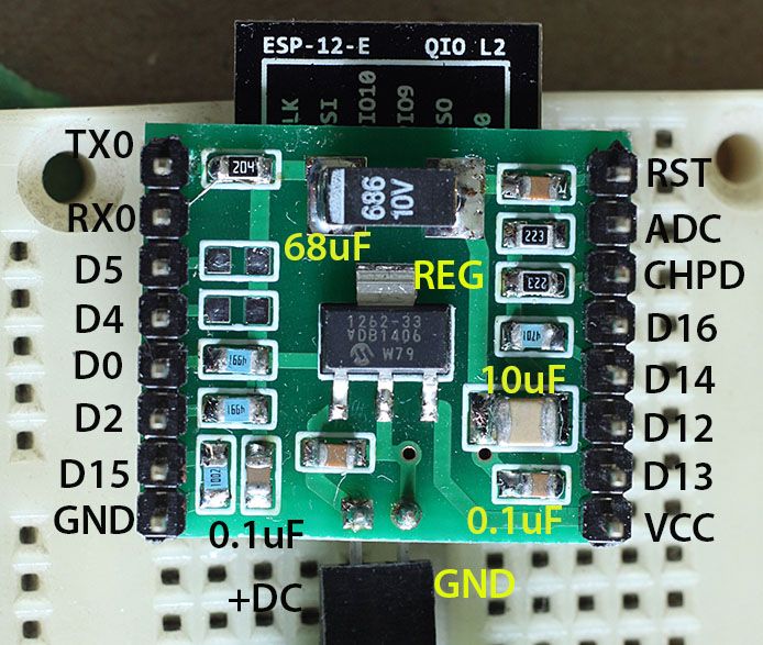
Pull up and pull down resistors, some required, some for convenience. Plus a linear regulator. I have used the little switching regulator, that you used, on some commercial products. I really like it.


