- Wed May 10, 2017 3:01 am
#65790
We take blink and breathing light as examples to learn the use of micropython on ameba. However, currently ameba doesn’t support Timer, and there is no breathing light demo.
Blink Program
Using micropython on ameba for the first time, we must burn micropython onto ameba board. The burning method is very simple. Download the following link and then unpack it. We will get a ram_all.bin file (if there is problem of unpacking under windows, think about unpacking under linux or virtual machine). Burn the file onto ameba board, and then we can use micropython on ameba. Of course we need a terminal (putty) to write micropython
Link: https://github.com/cwyark/micropython/releases/download/v1.8.3/ram_all.tar
After ameba is linked to PC, we need to install a driver. At the completion of installation, we can see MBED (a mobile device) in my computer. https://developer.mbed.org/media/downlo ... _16466.exe.
Then right-click->my computer->management->device manager->port. We can see the port number of ameba. Here you can see my port no. is COM7. 烧录方法:
Burning method:
After completing driver installation, you can see a mobile device MBED in my computer. Double click to open it. Copy the unpacked ram_all.bin file to MBED. Meanwhile you can see that the green light is flashing, which reflects burning. When it stops flashing, burning is completed.
After finishing preparation, open putty terminal. The following interface will appear. Follow the arrow to modify selection.
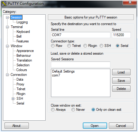
After finishing preparation, open putty terminal. The following interface will appear. Follow the arrow to modify selection.
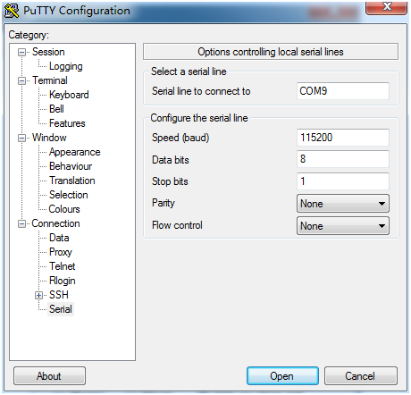
These are default selection of 115200 8 1 None None.
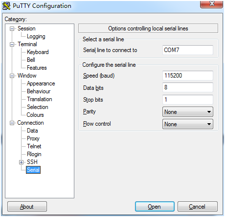
After finishing setting, click open. Then click enter key several times. There will be an interface as follows.
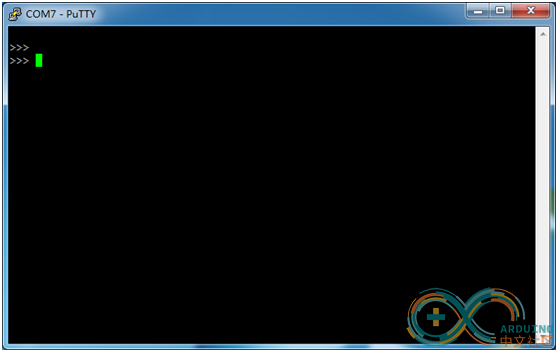
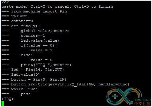
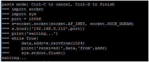
Press Ctrl+E in the terminal. There will be a paste command line as follows
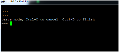
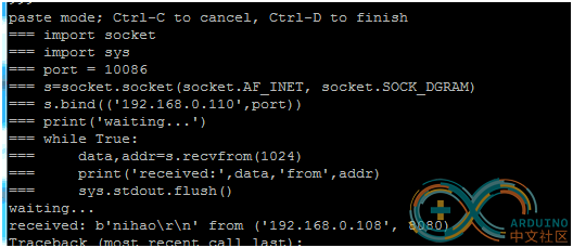
Copy the blink program and then right-click in the terminal to finish the copy as shown below. Press Ctrl+D for completing copy. Press Ctrl+C to cancel copy.
It is very simple. Led light is flashing. Press Ctrl+C for exit after completion (currently, ameba doesn’t support the command).
Use of micropython on esp32 esp32
Temporarily, esp32 doesn’t support Timer, therefore there is no breathing light demo.
Blink Program
Method for burning micropython firmware
Use the official programming tools to burn. Before burning, we need to compile micropython firmware first. Refer to the official compiling method. You can directly use my compiled firware: micropython firmware to save the trouble. Note that flash initial address of each firmware cannot be changed. Address of official firmware compiling method is:
[url=https://github.com/micropython/micropython-esp32/tree/esp32/esp32 ]https://github.com/micropython/micropython-esp32/tree/esp32/esp32 [/url]
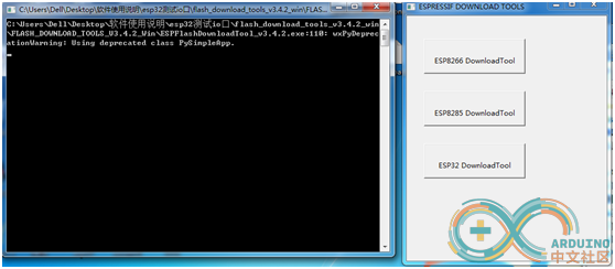
After downloading the official burning tool, double click the burning tool, as shown below:
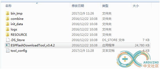
There will be two interfaces after opening:
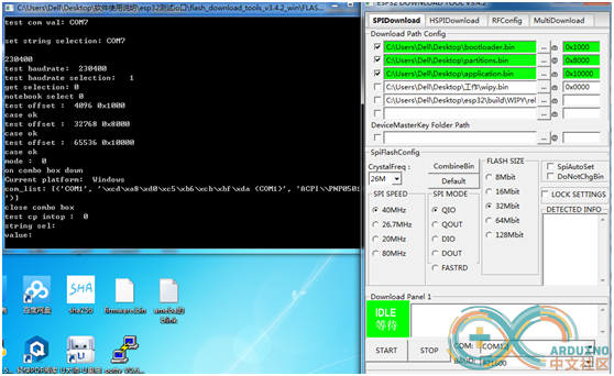
Click ESP32DownloadTool on the right interface. We can see the interface of burning firmware. Now we are not far from success. Keep going! At this time, import the three compiled or downloaded bin files of micropython into burning tool. Check the port no. in my computer. Right-click->my computer->management->device manager->port. Note: be sure the address is right, otherwise burning may not be successful or it cannot work normally after burning.
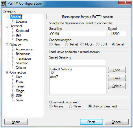
After burning, close burning tool. Open and operate terminal putty of micropython. Select port No. (COM12), connection type(Serial).
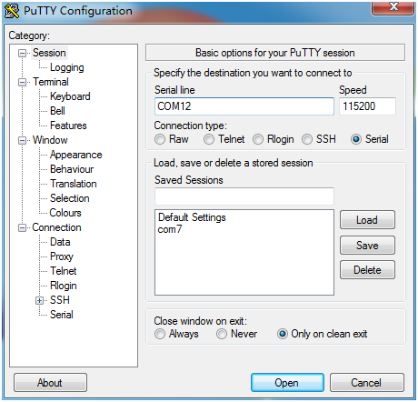
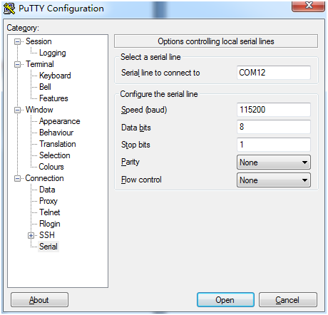
Other settings are as follows. Click Open after setting.
Press enter key several times after Open. We can enter micropython language at putty terminal.
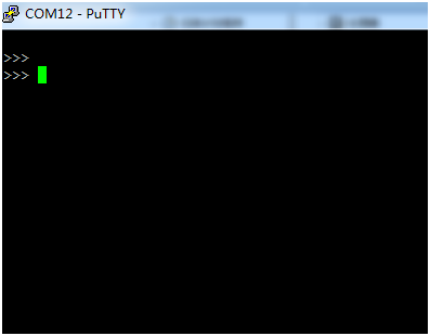
Press Ctrl+E to enter paste mode. Right-click in the mode to paste program. Press Ctrl+D to complete pasting. Micropython will execute the program of pasting.
Now led light is flashing. Isn’t it quite simple to light blink! After completion, press Ctrl+C to exit executing program. Led light stops flashing.
Use of micropython on esp8266
Blink and breathing light are supported on esp8266. Let’s learn how to operate blink and breathing light on esp8266 by using micropython!
Blink program
Breathing light program:
Firstly, we need to link esp8266 to PC, and then find the port no. of esp8266 in the same method as that of esp32 and ameba. My port no. here is COM9 (you need to find your own).
To use micropython on esp8266, we must burn the micropython firmware of esp8266 to board. There is compiled firmware on micropython official website for downloading. Address is: http://micropython.org/download.
Open and run terminal putty of micropython. Select port no. (COM9), connection type(Serial).
Other settings are shown below. Click Open after setting.
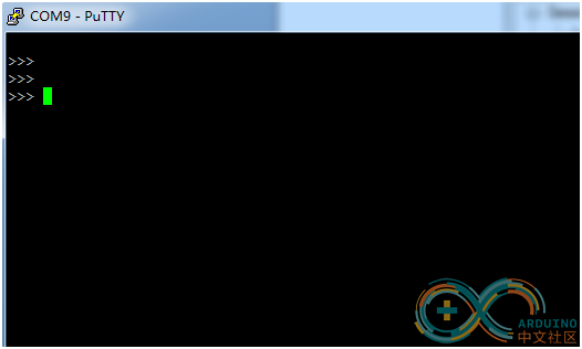
Press enter key several times after Open. We can enter micropython language at putty terminal.


Breathing light
After that we can realize blink in the same method as that of esp32 and ameba. There is a led light installed on esp8266 board, and is no need of external connection of led light. Method of finishing breathing light is also the same. I will save the trouble of introduction here.
IO port reading on esp32 platform
IO port reading program
Enter the read program of IO port to terminal for running. IO34 pin is connected to nothing, so what it read is low level, output 0. When we connect IO34 pin to 3.3V pin, what it read is high level, output 1.
Reference ESP8266 micropython- Tutorial 2: Micropython GPIO
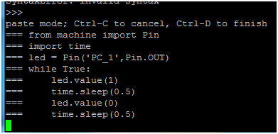
Blink Program
Code: Select all
   from machine import Pin
   import time
   led = Pin('PC_1',Pin.OUT)
   while True:
    led.value(1)
    time.sleep(0.5)
    led.value(0)
    time.sleep(0.5)
Using micropython on ameba for the first time, we must burn micropython onto ameba board. The burning method is very simple. Download the following link and then unpack it. We will get a ram_all.bin file (if there is problem of unpacking under windows, think about unpacking under linux or virtual machine). Burn the file onto ameba board, and then we can use micropython on ameba. Of course we need a terminal (putty) to write micropython
Link: https://github.com/cwyark/micropython/releases/download/v1.8.3/ram_all.tar
After ameba is linked to PC, we need to install a driver. At the completion of installation, we can see MBED (a mobile device) in my computer. https://developer.mbed.org/media/downlo ... _16466.exe.
Then right-click->my computer->management->device manager->port. We can see the port number of ameba. Here you can see my port no. is COM7. 烧录方法:
Burning method:
After completing driver installation, you can see a mobile device MBED in my computer. Double click to open it. Copy the unpacked ram_all.bin file to MBED. Meanwhile you can see that the green light is flashing, which reflects burning. When it stops flashing, burning is completed.
After finishing preparation, open putty terminal. The following interface will appear. Follow the arrow to modify selection.
After finishing preparation, open putty terminal. The following interface will appear. Follow the arrow to modify selection.
These are default selection of 115200 8 1 None None.
After finishing setting, click open. Then click enter key several times. There will be an interface as follows.
Press Ctrl+E in the terminal. There will be a paste command line as follows
Copy the blink program and then right-click in the terminal to finish the copy as shown below. Press Ctrl+D for completing copy. Press Ctrl+C to cancel copy.
It is very simple. Led light is flashing. Press Ctrl+C for exit after completion (currently, ameba doesn’t support the command).
Use of micropython on esp32 esp32
Temporarily, esp32 doesn’t support Timer, therefore there is no breathing light demo.
Blink Program
Code: Select all
from machine import Pin
   import time
   led = Pin(13,Pin.OUT)
   try:
     whileTrue:
       led.value(1)
       time.sleep(0.5)
       led.value(0)
       time.sleep(0.5)
   except:
     led.value(0)
Method for burning micropython firmware
Use the official programming tools to burn. Before burning, we need to compile micropython firmware first. Refer to the official compiling method. You can directly use my compiled firware: micropython firmware to save the trouble. Note that flash initial address of each firmware cannot be changed. Address of official firmware compiling method is:
[url=https://github.com/micropython/micropython-esp32/tree/esp32/esp32 ]https://github.com/micropython/micropython-esp32/tree/esp32/esp32 [/url]
After downloading the official burning tool, double click the burning tool, as shown below:
There will be two interfaces after opening:
Click ESP32DownloadTool on the right interface. We can see the interface of burning firmware. Now we are not far from success. Keep going! At this time, import the three compiled or downloaded bin files of micropython into burning tool. Check the port no. in my computer. Right-click->my computer->management->device manager->port. Note: be sure the address is right, otherwise burning may not be successful or it cannot work normally after burning.
After burning, close burning tool. Open and operate terminal putty of micropython. Select port No. (COM12), connection type(Serial).
Other settings are as follows. Click Open after setting.
Press enter key several times after Open. We can enter micropython language at putty terminal.
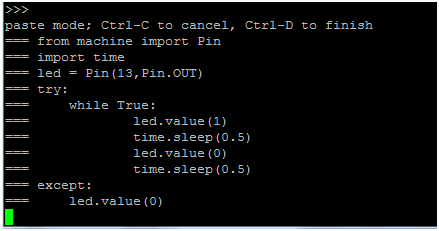
Press Ctrl+E to enter paste mode. Right-click in the mode to paste program. Press Ctrl+D to complete pasting. Micropython will execute the program of pasting.
Now led light is flashing. Isn’t it quite simple to light blink! After completion, press Ctrl+C to exit executing program. Led light stops flashing.
Use of micropython on esp8266
Blink and breathing light are supported on esp8266. Let’s learn how to operate blink and breathing light on esp8266 by using micropython!
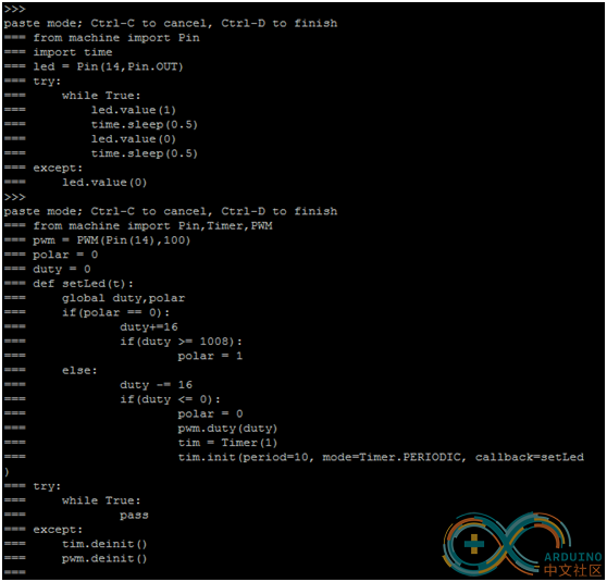
Blink program
Code: Select all
from machineimport Pin
import time
led = Pin(14,Pin.OUT)
try:
while True:
led.value(1)
time.sleep(0.5)
led.value(0)
time.sleep(0.5)
except:
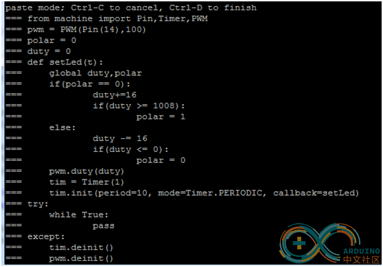
led.value(0)Breathing light program:
Code: Select all
from machineimport Pin,Timer,PWM
pwm =PWM(Pin(14),100)
polar = 0
duty = 0
def setLed(t):
global duty,polar
if(polar == 0):
duty+=16
if(duty >= 1008):
polar = 1
else:
duty -= 16
if(duty <= 0):
polar = 0
pwm.duty(duty)
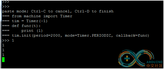
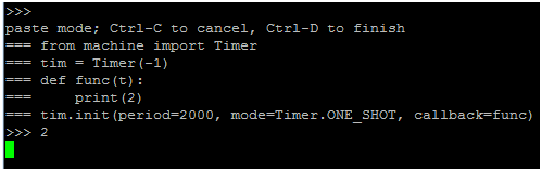
tim = Timer(1)
tim.init(period=10,mode=Timer.PERIODIC, callback=setLed)
try:
while True:
pass
except:
tim.deinit()
pwm.deinit()Firstly, we need to link esp8266 to PC, and then find the port no. of esp8266 in the same method as that of esp32 and ameba. My port no. here is COM9 (you need to find your own).
To use micropython on esp8266, we must burn the micropython firmware of esp8266 to board. There is compiled firmware on micropython official website for downloading. Address is: http://micropython.org/download.
Open and run terminal putty of micropython. Select port no. (COM9), connection type(Serial).
Other settings are shown below. Click Open after setting.
Press enter key several times after Open. We can enter micropython language at putty terminal.
Breathing light
After that we can realize blink in the same method as that of esp32 and ameba. There is a led light installed on esp8266 board, and is no need of external connection of led light. Method of finishing breathing light is also the same. I will save the trouble of introduction here.
IO port reading on esp32 platform
IO port reading program
Code: Select all
 from machineimport Pin
  import time
  button =Pin(34,Pin.IN)
  while True:
   print(button.value())
   time.sleep(1)
Enter the read program of IO port to terminal for running. IO34 pin is connected to nothing, so what it read is low level, output 0. When we connect IO34 pin to 3.3V pin, what it read is high level, output 1.
Reference ESP8266 micropython- Tutorial 2: Micropython GPIO