A place users can post their projects. If you have a small project and would like your own dedicated place to post and have others chat about it then this is your spot.

User avatar
By amadeuspzs
#91416 Hi all,

I couldn't find a (rechargeable) battery powered temperature/humidity sensor over MQTT that was cheap (Shelly sell one for £20) so over the last year I've made one using:
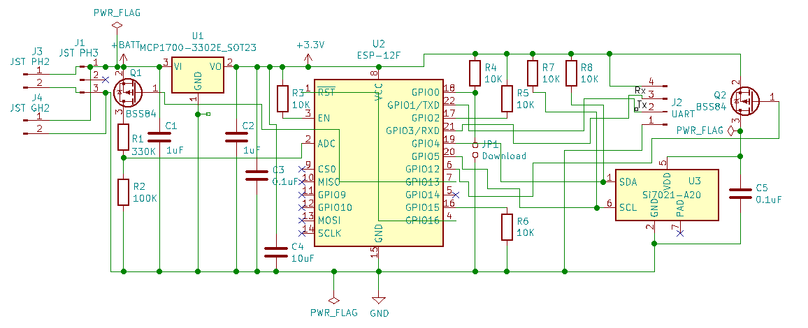
1. ESP-12F
2. Si7021 temp/humidity sensor
3. MCP1700 LDO
4. JST Li-Ion battery
5. Two BSS84 mosfets to switch on the temp sensor and voltage divider for battery voltage measurement

Image

Image

Lots of details on its project website and Github.

I've got to around 9 months usage on a 1200 mAh battery, which is better than my target of 6 months, although I note Shelly claim 18 months so any tips on further improving battery usage very welcome!

Here is the schematic:

Image

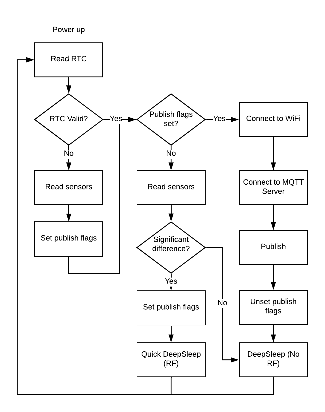
The software flow is:

Image

Total cost is around £8 per unit, which I could get down by using a cheaper sensor.

I've found the "1V" ADC to be pretty variable - that plus temperature variance of the voltage divider means the battery voltage measurement is not great.

Any feedback on hardware/software welcome!

Amadeus
User avatar
By schufti
#91425 a) you have to disable wifi for more stable measurement
b) you may have some leakage via the i2c pullups; try connecting them after the mosfet/direct to si.

the si draws very little current, so it might be sufficient to power it from gpio instead of using mosfet.
in standby (when not accessed) it uses a magnitude less (60nA vs ~50µA) than the esp12 so disconecting is allmost w/o effect.

p.s.: a direct connection between rst and gpio16 will give you a hard time resetting&uploading a new sketch during deepsleep periode as rst is pulled hard to vcc through gpio16. hard grounding might eventually damage gpio16. it is recommended to use a schotky diode between rst ->|- gpio16 instead.
User avatar
By amadeuspzs
#91429 Thanks for taking a look!

> you have to disable wifi for more stable measurement

Measurements occur during the WAKE_RF_DISABLED cycle, with WiFi.mode(WIFI_OFF) for safe measure. I am manually calibrating Vref on each chip with a multimeter.

When I moved from calibration to one location which was 10C hotter, the voltage measurement jumped from 3.95V (correct) to 4.17V and is staying there. I've just re-measured the actual battery voltage with a multimeter and it is 3.92V, even though the temperature is now 7C cooler than during calibration (this unit is in a greenhouse). Maybe humidity affects the reading?

I am aware that input impedance matters, and I could try dropping the total resistor values from 430K to e.g. 4.3K, which with the mosfet shouldn't impact power consumption too much. But am I unrealistic in expecting to get +- 20mV accuracy from the ADC? 10 bit resolution should be 1mV?

> you may have some leakage via the i2c pullups; try connecting them after the mosfet/direct to si.

Great spot - I can route them to the mosfet vcc output.

> 60nA standby current

Yes this is small, now that I recalculate what this is at 9 months it is only 0.4mAh! So I will ditch this mosfet to simplify the circuit.

> direct connection between rst and gpio16

Stupid questions but I am current in understanding that:

1. There is no internal PULLUP on RST (ESP-12F datasheet)
2. This doesn't matter as according to the ESP8266EX datasheet, `EXT_RSTB goes high after VDD33: 0.1ms` ie. it is held high by the chip?
3. Therefore, if you leave RST floating (rst ->|- gpio16 with gpio16 high), it will be held high internally?
4. When gpio16 is held low, current can flow through the diode and trigger a reset?
5. By using a diode, you are protecting RST from "external vcc" in addition to the internal connection which could damage it over time?

The existing process for programming is to power cycle with the download jumper connected. I'm looking to move this all to pogo pins for less components, so I could short GPIO0 and rst in the pogo adapter to GND to trigger a download cycle. The only reason for splitting out the download jumper is I often access serial debugging, but I could just disconnect the GND short in the adapter (I'd probably debug over battery power so would only need GND, Rx and Tx anyway)?

Thanks again,

Amadeus
User avatar
By schufti
#91431 Hi,
in some ancient thread somebody looked at the stability and drift of the adc and the conclusion was sth like 7 bit at best. There are ways to improve like using to fast conversion and averaging but just to define battery state it is not worth the effort. The resistors are a little bit on the high side though; maybe a little cap on the adc pin to decrease dynamic impedance?

Acually there should be a weak internal pullup on rst. Even 12F modules differ on internals. The next best thing to the diode would be a resistor; a value of 470Ohms to 1k seems to work best.
The flashing problems only occur if trying to reset / flash "live" during a deepsleep cycle.
After repowering and several resets without entering deepsleep it shouldn't be a problem (gpio16==input).