Use this forum to chat about hardware specific topics for the ESP8266 (peripherals, memory, clocks, JTAG, programming)

User avatar
By edwin
#58368 Very interesting read. Especially your experience with the HT7333

I started out using an AP2112. That is the same one as on the (new) Huzzah.
Have a TP4056 feeding/charging a LiPo cell. I feed the TP4056 with a 6 Volt Solar panel. TP4056 goes to an AP2112 that delivers a nice 3.3 Volt (dropvoltage 125mV at 300mA). Have to be a bit careful with the AP2112 as it can only take 6V max.

As I saw the HT7333 recommended left and right I tried that too. I am not sure what the dropvoltage of that one is at a decent current, it is 90-100mV at 40mA, which is a low current, but the ESP8266 operated well while sending I didnt measure the voltage (I may do so) as it was operating well. The HT7333 is available in a TO92 I think which makes it a bit more attractive to solder.

Also tried the RT9013. That is the same one as on the Wemosboard. Works well in the circuit described above.

I have to add that it hasn’t been very sunny, but as as my LiPo remained charged above 3.7 everything functioned well. Still got to see what happens if it drops to 3.3 Volts, but I presume that will be OK too as I have fed an ESP8266 with 3 Volts and it worked well.

considering prices USD
AP2112 = 18.5 cts
HT7333 = 12.5 cts
RT9013 = 16 cts
XC6203 = 23.8 cts

I think I may stick to the AP2112. Let me add though that it has an enable pin that needs to be pulled high through a 10k resistor. Could consider that a nuisance or an option.
The HT7333 is handy if yr eyesight isnt that great but considering the datasheet doesnt give much info for higher currents I guess I will just leave it.

Maybe slightly letting the topic creep: I also tried a Wemos battery shield which I directly fed (through the USB port) with a 6V solarpanel and a battery attached (darned different connectors).

That actually works well and is an easy way of solar feeding the Wemos D1 mini
User avatar
By ErikLem
#60382 It's been a few weeks, time to report back.
I've by now received the XC6203P332PR and the TPS73633. Because they are not exactly breadboard friendly, I decided to create a prototype board so that I could do some proper testing.

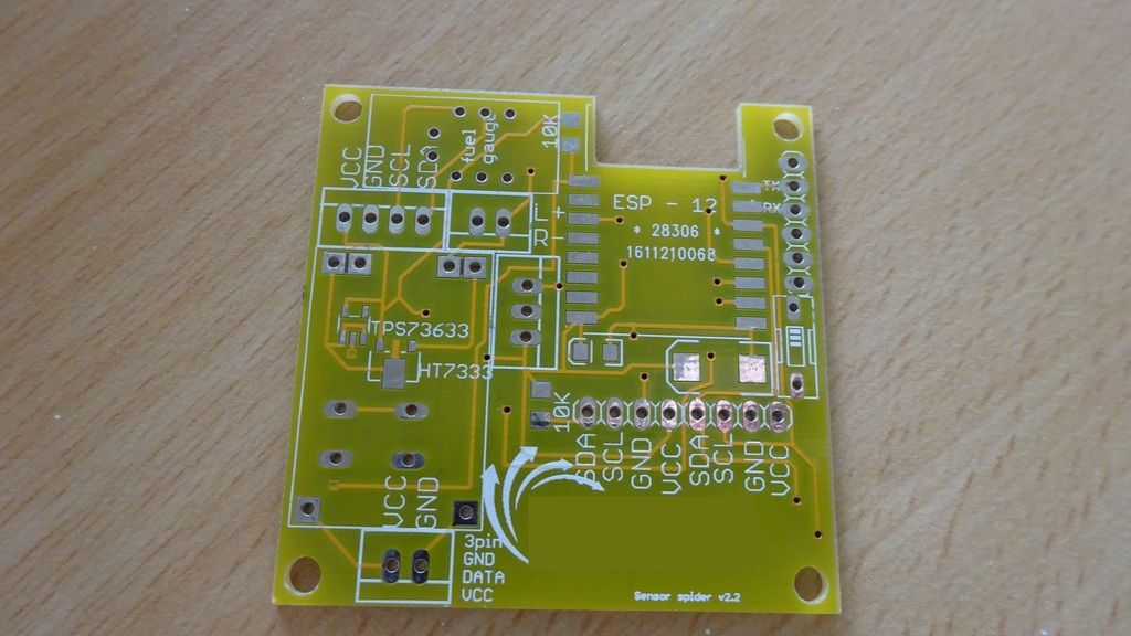
I made the board in such a way that I could choose weather to use the XC6203P332PR or the TPS73633. Furthermore the board has some pullups / pulldowns, room for 2 capacitors, room for the TP4056 board and room for the Sparksfun lipo fuel gauge, room for a onewire sensor (like a Ds18B20) and room for 3 i2c sensors. oh yes, and of course room for the ESP-12. On the bottom left side, I have the connector for the 5v input, and above the TP4056 the connector for the battery.

Image

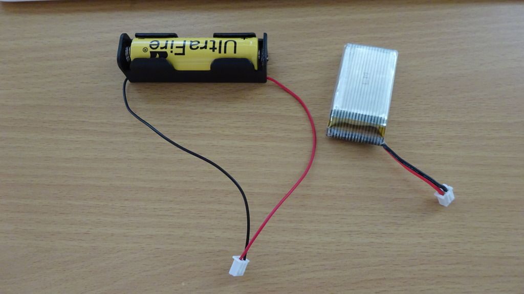
I started out testing with these two batteries:

Image

Charging them worked like a charm, but unfortunately, running the ESP did not work very well. As long as the AC adapter was plugged in, the esp is getting a proper 3.3v with either the XC6203P332PR or the TPS73633, however, as soon as the ac adapter is disconnected , there is only between 0.2v and 1.0v left on the ESP, so obviously something is going wrong.

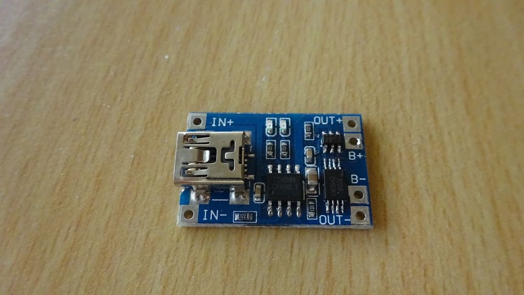
It seems like the TP4056 is the offending part. The board had 4 connectors:

Image

2 for the AC adapter:
in +
in -

2 for the battery:
b+
b-

and 2 that I thought would be suitable to feed to the voltage regulators:
out+
out-

I'm was starting to think that that last assumption was wrong. When I assemble a board with just the power connectors, a XC6203P332PR or a TPS73633 and the TP4056, I saw that on the B+ and B- i had around 4.0v , while on the out+ and out- the voltage already drops to 1.0v.

However, when I just hooked a battery up to a TP4056 board, without the voltage regulator on, I did not see that behavior, the voltage on out+ and out- is then actually the same as on b+ and b-

Most likely cause now seems a error in my board, I'm however unable to spot what the problem is
any ideas?

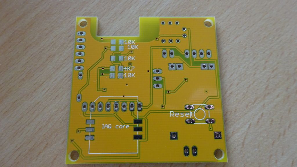
This is the front and the back of the board :

Image

Image
User avatar
By ErikLem
#60579 After quite some more testing, I'm now pretty sure that the problem is not in my board.

I set up this contraption:

Image

The battery is plugged into the B+ and B- of the tp4056 board, the OUT+ and OUT- of the board go into the XC6203P332PR, and the output of that goes into the ESP.

Sometimes, that give me the desired voltage of around 3.3v. Lots of times however, it gives me voltages like these:

Image

Plugging the battery in and out a few times sometimes it will all of a sudden give a proper voltage again.

Next step: see if the problem is with the tp4056 board or with the XC6203P332PR. I did not have any luck with the TPS73633, that chip is getting smoking hot, so probablt something else is going on there...