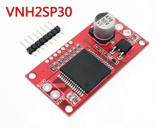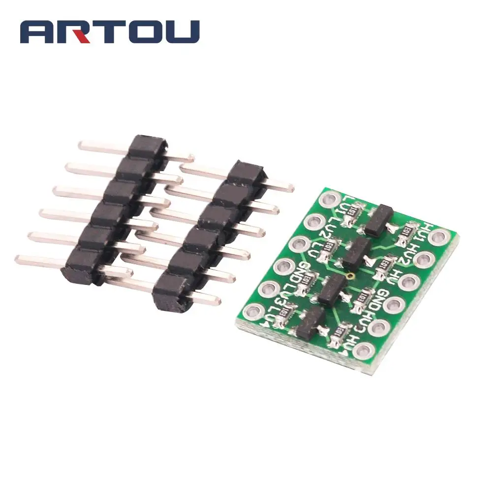
A converter does not give enough intensity with

I succeeded with

But the controls are reversed (not serious) and when the engine stops through R2 28 mA and when running is 4mA.
How to reverse so that at rest we have a weak current ?
Explore... Chat... Share...


rudy wrote:If you are only trying to provide an input to the VNH2SP30 then you don't need to use 200 Ohms. Change the resistor to 2K2, or something at that level.
It takes about 20-25 seconds for home assistant c[…]
I tried to upgrade tof my sonoff basic R2 with the[…]
a problem Perhaps you want to define "Probl[…]
Rebooting your router will not give you a faster I[…]
There are no other notifications from esptool.py i[…]
Using the Arduino IDE, you'll learn how to set up […]
In this project, you will post to Twitter using an[…]
In this project, we will build a water level contr[…]
I guess I'm late, but I had the same problem and f[…]
Last night I received my first D1 Minis for a lear[…]
Although I am aware that this is an old post, I fe[…]