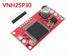
-->
Page 1 of 2

Use with a VNH2SP30

PostPosted: Sat Feb 09, 2019 2:36 pm
by froussel
I am trying to control the PWM pin of a VNH2SP30 that triggers at 3.7V under 5mA with an ESP8266
Image

A converter does not give enough intensity with
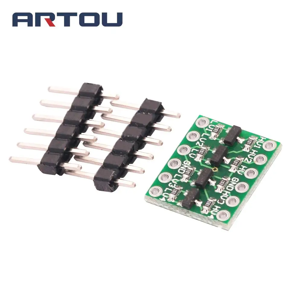
Image

I succeeded with
Image
But the controls are reversed (not serious) and when the engine stops through R2 28 mA and when running is 4mA.
How to reverse so that at rest we have a weak current ?

Re: Use with a VNH2SP30

PostPosted: Sat Feb 09, 2019 3:22 pm
by rudy
If you are only trying to provide an input to the VNH2SP30 then you don't need to use 200 Ohms. Change the resistor to 2K2, or something at that level.

If you are trying to also drive an LED with that signal, then I would suggest using a buffer for the LED alone.

If you want to invert the logic level back to normal, then use two transistor stages.

Maybe I am not understanding your problem correctly. :?

Re: Use with a VNH2SP30

PostPosted: Sat Feb 09, 2019 4:25 pm
by froussel
rudy wrote:If you are only trying to provide an input to the VNH2SP30 then you don't need to use 200 Ohms. Change the resistor to 2K2, or something at that level.


200 ohms because the VNH pulls 5mA, with a resistance of 2.2K the tension crumbles and goes well below the 3.7V necessary

Which schema with 2 transistors ?

Re: Use with a VNH2SP30

PostPosted: Sun Feb 10, 2019 7:42 am
by btidey
I think you can use common base method for this to avoid inversion in single stage.

CBase.jpg


GPIO high turns transistor off and allows output to be pulled up. GPIO low turns transistor on and sinks current. Note common base does not amplify current so any sink load goes through GPIO and should be kept below about 10mA.

If you need higher current then I think you will need 2 transistor version.