
- Sun Dec 15, 2019 7:28 am
#84914
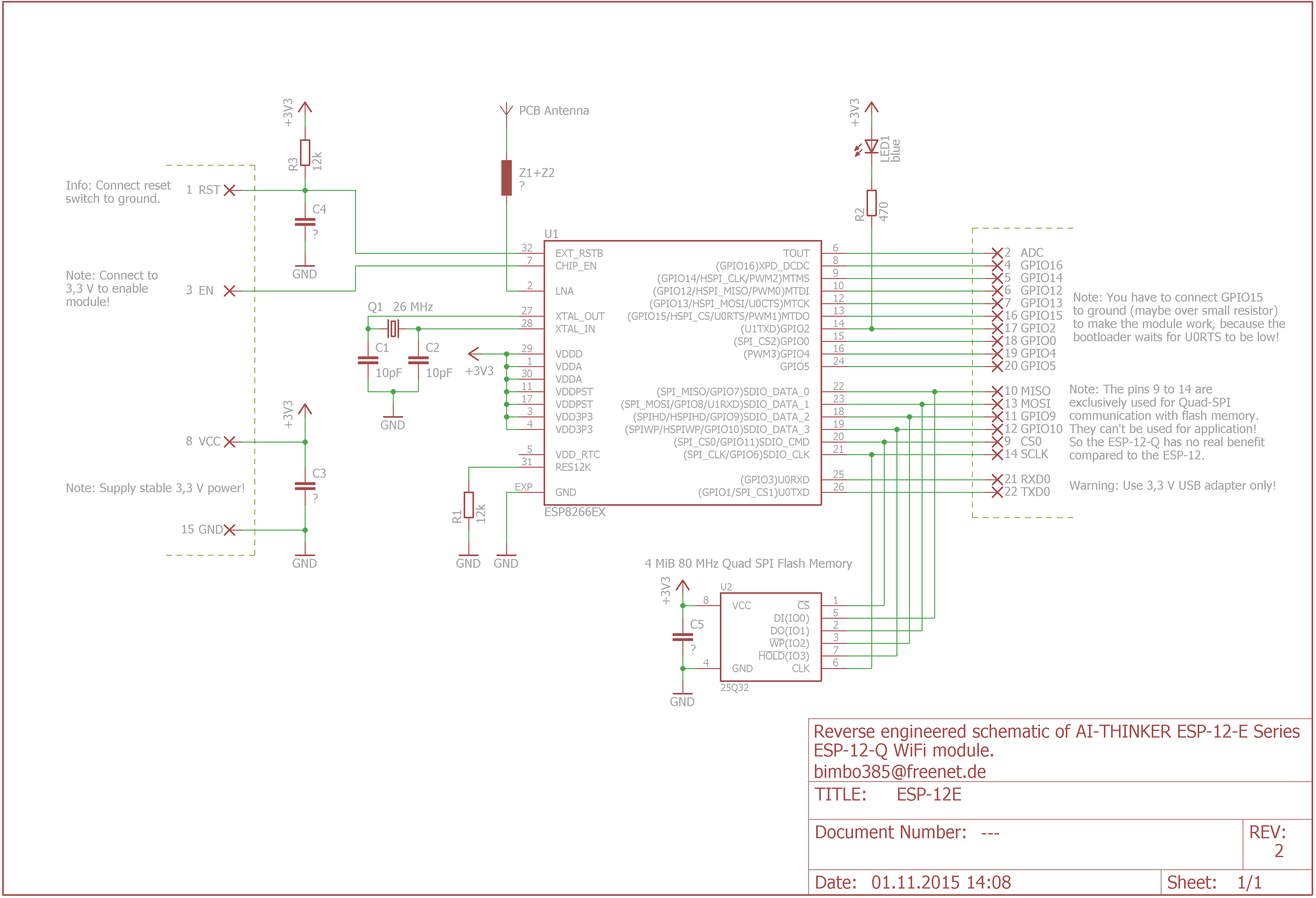
I'm using voltage divider to identify which out of 5 buttons was pressed. I have connected the output voltage to analog A0 pin and D4 (gpio2) to catch interrupts. The problem is that I'm not getting expected measurements. I know about the voltage divider (I am using NodeMCU v3) and that it shows results within the range 0-1023. I was searching through documentation and schematics and found out that there is a blue led and 470 ohm resistor connected to gpio2 but even now I'm not getting expected results. I am using online circuit simulator in attempt to build the circuit and this is how it looks right now:

The expected values are: ~20mV, ~120mV, ~220mV, ~300mV, ~490mV.
What I am getting with this current simulation: 23mV, 227mV, 409mV, 502mV, 563mV.
Here is schematic with the diode connected to gpio2:
Am I missing something? I would like to know where I've made a mistake creating the circuit.
The expected values are: ~20mV, ~120mV, ~220mV, ~300mV, ~490mV.
What I am getting with this current simulation: 23mV, 227mV, 409mV, 502mV, 563mV.
Here is schematic with the diode connected to gpio2:
Am I missing something? I would like to know where I've made a mistake creating the circuit.


