Can't get ESP-01 to work
Hi guys,
During these isolation days I decided to play with some ESPs I got lying around which I never used.
I successfully installed and programmed some D1 minis with MicroPython, and now I wanted to build a smaller project.
I got 2 ESP-01s with 1MB flash size, but I really can't get them to work. I can put them in flashing mode and flash some firmware on them, but that's it. Once I disconnect GPIO-0 from GND my computer doesn't see the device anymore, and I can't get any serial prompt. If leave the pin grounded my computer can't see it but I obviously get no serial prompt anyway.
To connect the board to the computer I used a cheap TTL-USB adapter like this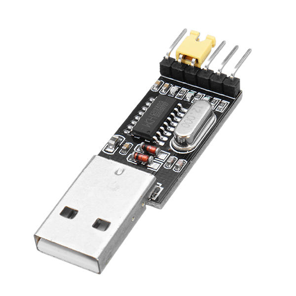 and did the proper wiring. Tried exchanging adapter and board since I got more than 1, but it's the same story. The wiring is ok since I can flash firmware. I did unplug and plugged again the ESP everytime I flashed something. Also, when I disconnect ground from GPIO-0 two of three LEDs stay constantly lit on the adapter instead of one, but I can't find what these status LEDs stand for (except for power on).
The reason why I need serial communication is because I want to use Micropython, and it doesn't work whether it's a python REPL, AT commands or a simple Serial.print()
What could it be? I'm going crazy!
During these isolation days I decided to play with some ESPs I got lying around which I never used.
I successfully installed and programmed some D1 minis with MicroPython, and now I wanted to build a smaller project.
I got 2 ESP-01s with 1MB flash size, but I really can't get them to work. I can put them in flashing mode and flash some firmware on them, but that's it. Once I disconnect GPIO-0 from GND my computer doesn't see the device anymore, and I can't get any serial prompt. If leave the pin grounded my computer can't see it but I obviously get no serial prompt anyway.
To connect the board to the computer I used a cheap TTL-USB adapter like this
and did the proper wiring. Tried exchanging adapter and board since I got more than 1, but it's the same story. The wiring is ok since I can flash firmware. I did unplug and plugged again the ESP everytime I flashed something. Also, when I disconnect ground from GPIO-0 two of three LEDs stay constantly lit on the adapter instead of one, but I can't find what these status LEDs stand for (except for power on).The reason why I need serial communication is because I want to use Micropython, and it doesn't work whether it's a python REPL, AT commands or a simple Serial.print()
What could it be? I'm going crazy!