- Sat Jul 25, 2015 2:20 pm
#24249
I am guessing that we all build test circuits on breadboards or stripboard using ESP-1s or ESP-12s (these days). I am wondering what your circuit looks like?
To start the ball rolling, here is mine:
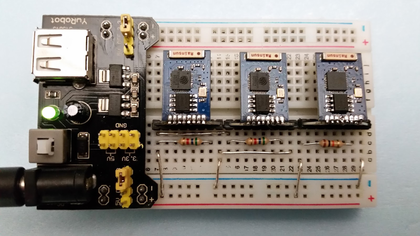
I have an MB102 power supply that can take input from a wall wart or a USB. It is switched to 3.3V. I use ESP-12s that are plugged into female sockets on the breakout board. If I fry my ESP-12, I can plug in a new one quickly.
There are two sets 8-socket female sockets for plugging in breadboard links.
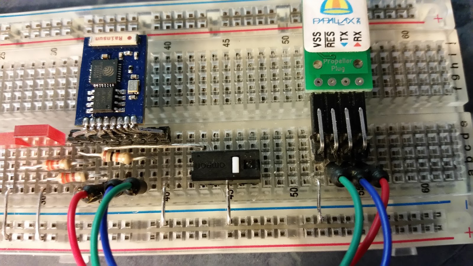
On the bottom left is a reset switch.
On the bottom right is a jumper that brings GPIO0 to GND or +ve.
At the top right is a second jumper that connects REST to DSR on the USB->UART used for flashing.
The 2nd USB->UART is used for debugging.
I didn't spend any time on layout management but space wasn't a consideration for my needs. Things that I would add on a second iteration (or a modification of this one) would be:
- sockets for an ESP-1
- LEDs with current limiting resistors with sockets
- Perhaps switches instead of jumpers
If you have the inclination, post your setups and lets see if we can find patterns or tricks we can share with each other.
Neil
To start the ball rolling, here is mine:
I have an MB102 power supply that can take input from a wall wart or a USB. It is switched to 3.3V. I use ESP-12s that are plugged into female sockets on the breakout board. If I fry my ESP-12, I can plug in a new one quickly.
There are two sets 8-socket female sockets for plugging in breadboard links.
On the bottom left is a reset switch.
On the bottom right is a jumper that brings GPIO0 to GND or +ve.
At the top right is a second jumper that connects REST to DSR on the USB->UART used for flashing.
The 2nd USB->UART is used for debugging.
I didn't spend any time on layout management but space wasn't a consideration for my needs. Things that I would add on a second iteration (or a modification of this one) would be:
- sockets for an ESP-1
- LEDs with current limiting resistors with sockets
- Perhaps switches instead of jumpers
If you have the inclination, post your setups and lets see if we can find patterns or tricks we can share with each other.
Neil
You do not have the required permissions to view the files attached to this post.
Free ESP8266 book available for download here.