prototype bootup problems
hello all 
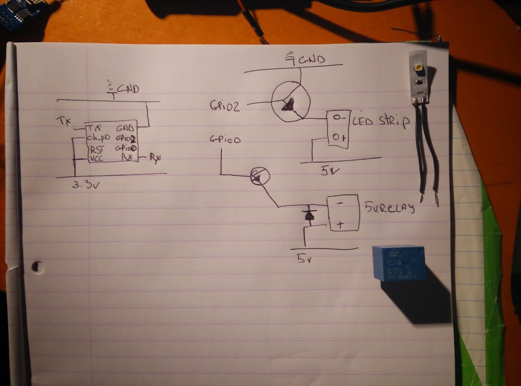
I'm trying to control a 5V LED-strip and 5V relay with an ESP-01 module. In the image below, you can see the circuit I want to design / use.
Because I'm still an (PCB) amateur and don't have the needed schooled knowledge, I'm having a problem to which I don't have an answer (YET :p ).
If I first start the microcontroller, and then connect the GPIO pins to NPN transistor, it works. But if the GPIO ports are already connected on the power-up of the ESP module, I don't receive a response from my module.
The errors that occured:
- If only the GPIO 0 is connected to the NPN on the power-up, I receive garbage in my serial monitor.
- If only the GPIO 2 is connected to the NPN on the power-up, the blue light remains lighted with no reaction on any command in the serial monitor.
- If both are connected to the NPN on the power-up, the blue led lights and the GPIO's doesn't react.
Solutions I was thinking about:
- The GPIO 0 was pulled to the ground on the power-up, resulting to flash mode of the ESP module.
* I've tried to resolve it with pull-up resistors, but this didn't work (after this I noticed that the chip didn't go into flash mode).
I hope someone can help me with this problem.
Kind regards,