esp-12 white mounting board - scematics
Hi i just bought esp-12 module with an "IO adapter plate" - it is that white mounting breakout board that has a few smd components on top (resistors??) and a place for a component on the bottom (a voltage regulator??)
Anyone knows what are the exact schematics for this board? i googled 20 minutes could not find it it is easy enough to visually trace the lines, but what are the values of the resistors? and is the regulator required or optional etc
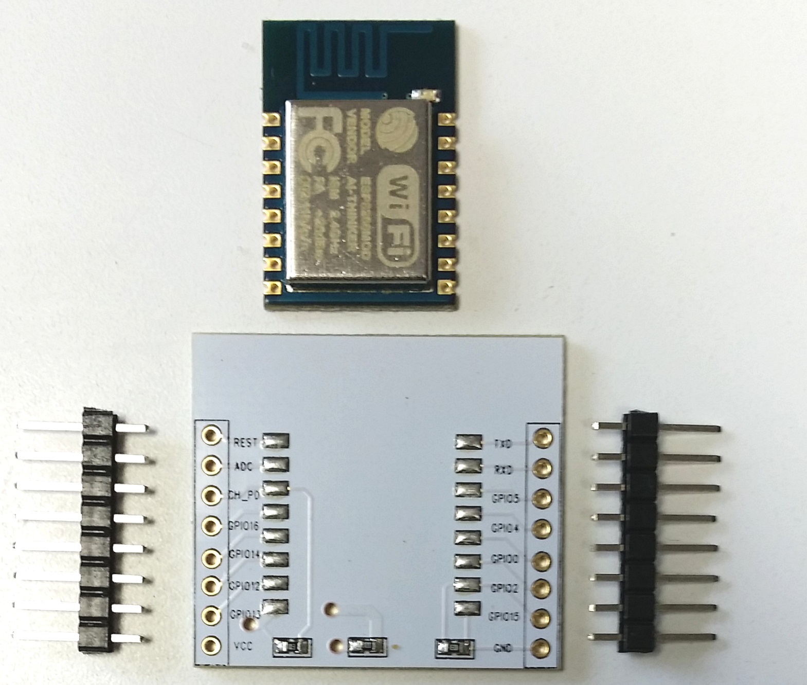
Board is similar to this:
Anyone knows what are the exact schematics for this board? i googled 20 minutes could not find it
Board is similar to this: