So you're a Noob? Post your questions here until you graduate! Don't be shy.

User avatar
By MeMagic
#87172
rudy wrote:You have Vcc and Gnd reversed on the connections for the transistor of the optocoupler and R1. Hopefully that is just an error in the schematic.

It's due to my "competence", it is not necessarily correct. Actually, if I check voltage on the exit it is around 3V. If it is connected inversely, the voltage is much less. At least, I had found that this would be correct. In fact the real schema is working, not sure for my sketch :)
User avatar
By schufti
#87182 and .. I can't find a gnd connection between the motor driver (pin 1?) and the esp board.
This is why I prefer a good picture from the real "construction" and not a - mostly euphemistic/idealized - capture as schematic; experience shows that the correlation between those two is often very weak.
User avatar
By MeMagic
#87188
schufti wrote:and .. I can't find a gnd connection between the motor driver (pin 1?) and the esp board.
This is why I prefer a good picture from the real "construction" and not a - mostly euphemistic/idealized - capture as schematic; experience shows that the correlation between those two is often very weak.

Well, let me tell you that you are definitely right! There is no GND connection between +5V and +3v3. Actually, the real DRV8833 module is a little bit different like the one found on this link: https://mvdlande.wordpress.com/2019/06/ ... er-module/
I will try later the system with the power unit GNDs connected and will come back with the result.
User avatar
By MeMagic
#87193
schufti wrote:and .. I can't find a gnd connection between the motor driver (pin 1?) and the esp board.
This is why I prefer a good picture from the real "construction" and not a - mostly euphemistic/idealized - capture as schematic; experience shows that the correlation between those two is often very weak.

Hi again!
I have tested the schema with a GND connection between DRV8833 module and ESP-12 - it makes no difference. Even more, I have noticed that even if I disconnect the pins that go to DRV8833, the signal from optocoupler is OK until I don't send HIGH to adjacent pins - GPIO12 and/or GPIO13. If there is a HIGH output signal on either of this pins, the GPIO14 switches continuously even if there is no mechanical action (covering or opening) on the optocoupler. So, from my short experience, I'd say that the ESP is defective. Once again, the components I'm using are following:
DRV8833 module - Image
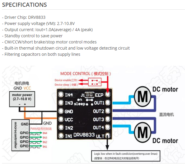
ITR9608 - datasheet https://www.digchip.com/datasheets/part ... 08-pdf.php
The schema is like this - https://drive.google.com/file/d/1NilxQe ... sp=sharing
Accordingly to the bottom view of the optocoupler in it's datasheet the optocoupler is connected to GND at Cathode directly and at Emitter via 10kOhm (pins 2 and 4).