Re: more than 4 pinmode give wdt reboot
thanks Rudy and Reaper,
I've tried all the different board settings, i'm back to
Generic ESP8266 Module, 80Mhz, 40Mhz, DIO, 512k (64K PSIFFS), ck, Disabled, None
but none make any difference (unless I choose a setting way out of spec).
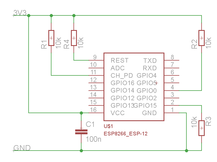
Whilst the tutorial i'm using
http://www.instructables.com/file/FCH0MSCI697OYRQ/
doesn't have any external resistors i notice some others are using 5-10k resisotrs to perform pull ups,
should i be using them?
A picture of my setup is here:
I've tried all the different board settings, i'm back to
Generic ESP8266 Module, 80Mhz, 40Mhz, DIO, 512k (64K PSIFFS), ck, Disabled, None
but none make any difference (unless I choose a setting way out of spec).
Whilst the tutorial i'm using
http://www.instructables.com/file/FCH0MSCI697OYRQ/
doesn't have any external resistors i notice some others are using 5-10k resisotrs to perform pull ups,
should i be using them?
A picture of my setup is here: