more than 4 pinmode give wdt reboot
so this is a wierd one and i have no idea what's going on.
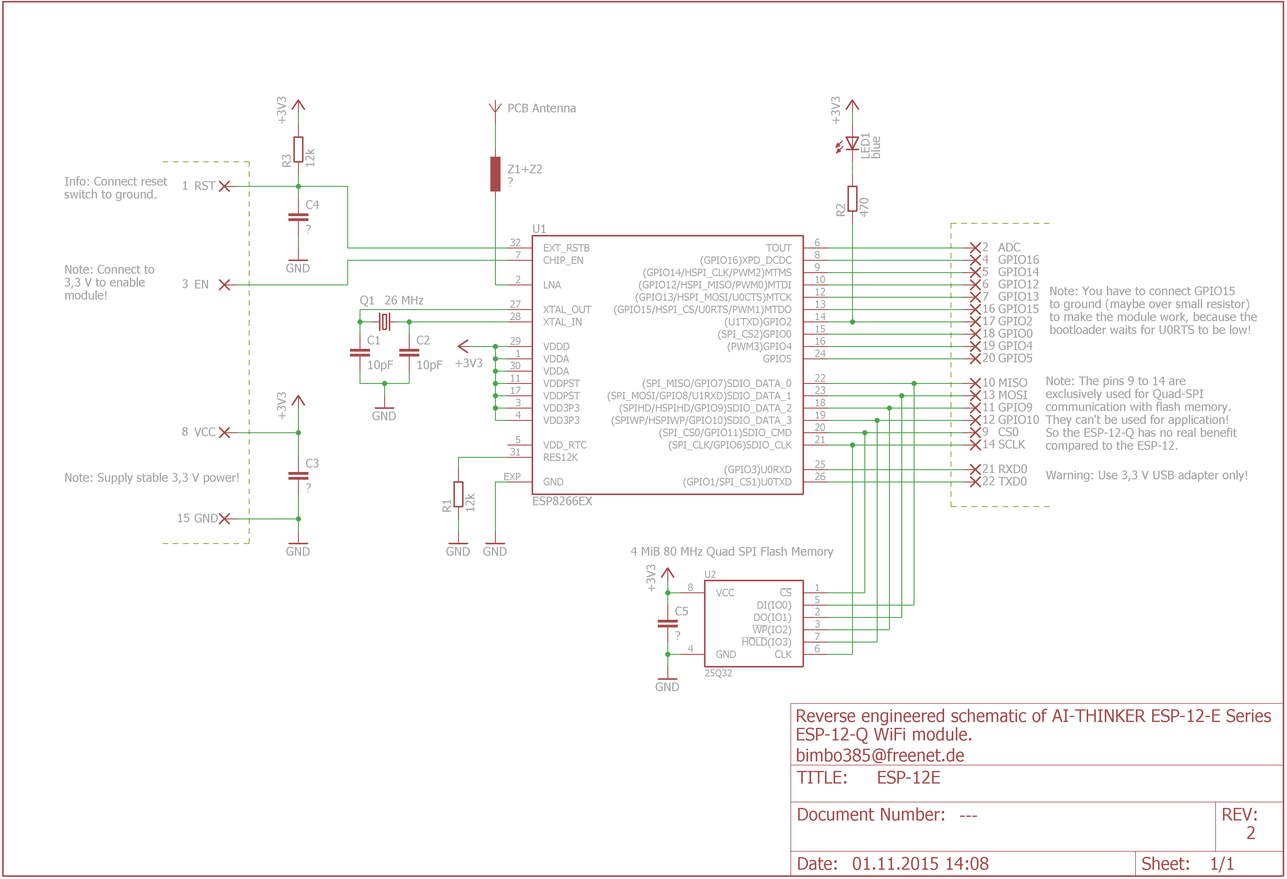
I have an ESP-12e module
this is my code:
this results in the wdt kicking in and my code not running.
if i comment out any one of the pinmode lines, it then works.
it doesn't matter which pinmode lines i comment out, if there are 5 or more it crashes.
Things i've tried:
loading up the normal blink example (works fine)
powercycling the module (no change)
using a different power supply (i'm using a 1amp linear bench top power supply) it never draws more than 180ma
soldering a 10uf capacitor across the Vcc and gnd of the module (no change)
using esptool.py to flash the nodemcu firmware and the original AT firmware (both work fine, then i go back to the code above and the same thing happens).
i haven't tried a different module as this thing is soldered directly to a few buttons leds and a servo so i'm really reluctant to unsolder and start again. I can also use the servo or blink the leds (as long as i don't have more than 4 pinmode lines.
can anyone help?
I have an ESP-12e module
this is my code:
Code: Select all
//ok lets declare them
int ServoSignal = 4;
int RelaySignal = 5;
int IRSend = 9;
int IRRec = 10;
int LEDClosed = 12;
int LEDOpen = 13;
int ButtonOpen = 14;
int ButtonAC = 16;
int ButtonBoom = 0; //this is using the adc do not use yet, placeholder only

void setup() {

  // put your setup code here, to run once:
//ok lets declare them
  pinMode(ServoSignal, OUTPUT);
  pinMode(RelaySignal, OUTPUT);
  pinMode(LEDClosed, OUTPUT);
  pinMode(LEDOpen, OUTPUT);
//  pinMode(IRSend, OUTPUT);
 // pinMode(IRRec, INPUT);
  pinMode(ButtonOpen, INPUT_PULLUP);
//  pinMode(ButtonAC, INPUT_PULLUP);
//  pinMode(ButtonBoom, INPUT_PULLUP);
   Serial.begin(115200);
Serial.println("i'm in the setup.");
}

void loop() {
  // put your main code here, to run repeatedly:
Serial.println("i'm running.");
}
this results in the wdt kicking in and my code not running.
if i comment out any one of the pinmode lines, it then works.
it doesn't matter which pinmode lines i comment out, if there are 5 or more it crashes.
Things i've tried:
loading up the normal blink example (works fine)
powercycling the module (no change)
using a different power supply (i'm using a 1amp linear bench top power supply) it never draws more than 180ma
soldering a 10uf capacitor across the Vcc and gnd of the module (no change)
using esptool.py to flash the nodemcu firmware and the original AT firmware (both work fine, then i go back to the code above and the same thing happens).
i haven't tried a different module as this thing is soldered directly to a few buttons leds and a servo so i'm really reluctant to unsolder and start again. I can also use the servo or blink the leds (as long as i don't have more than 4 pinmode lines.
can anyone help?
