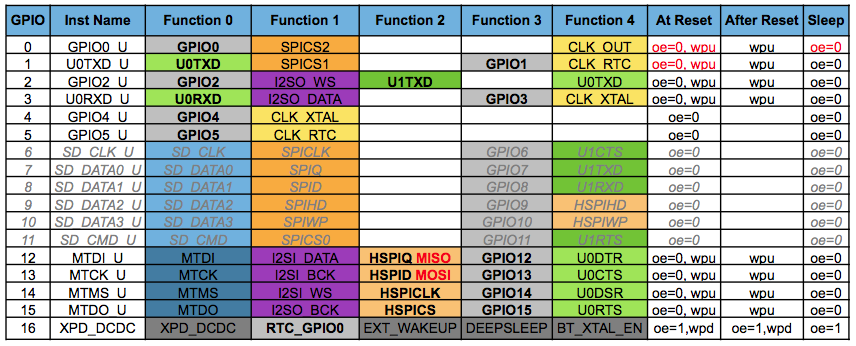
I'm a bit desperate, because I tried to build a NodeMCU powered WiFi-Clock using a 4 digit seven segment display. As shown in the code block my programming skills are very poor.
Flashed on the ESP8266 the code just shows 3 digits and the forth digit is dark. Not every number is displayed correctly, BUT I checked the wiring (including resistors) merely a thousand times.
I just need a helping hand, giving me advice to make this display work correctly. Would be awesome!
#include <ESP8266WiFi.h>
#include <NTPClient.h>
#include <WiFiUdp.h>


// ESP8266 Pins
int aPin = 14;  //         A
int bPin = 16;  //    ________
int cPin = 1;  //    |        |
int dPin = 13;  // F |        |  B
int ePin = 15;  //   |   G    |
int fPin = 0;  //    |________|
int gPin = 10;  //   |        |
int GND1 = 2; //     |        |
int GND2 = 4; //   E |        |   C
int GND3 = 5; //     |________|
int GND4 = 3; //
int dPnt = 12;//         D       O dPnt

int DTime = 1; //delay für Itterationen, 16ms default, 4 ms jetzt


// Netzwerk-Credentials
const char *ssid     = "ssid";
const char *password = "password";

// NTP Client
WiFiUDP ntpUDP;
NTPClient timeClient(ntpUDP, "pool.ntp.org");

void setup()
{
  pinMode(aPin, OUTPUT);
  pinMode(bPin, OUTPUT);
  pinMode(cPin, OUTPUT);
  pinMode(dPin, OUTPUT);
  pinMode(ePin, OUTPUT);
  pinMode(fPin, OUTPUT);
  pinMode(gPin, OUTPUT);
  pinMode(GND1, OUTPUT);
  pinMode(GND2, OUTPUT);
  pinMode(GND3, OUTPUT);
  pinMode(GND4, OUTPUT);
  pinMode(dPnt, OUTPUT);

  // Serial Monitor
  Serial.begin(115200);

  // Connect to Wi-Fi
  Serial.print("Connecting to ");
  Serial.println(ssid);
  WiFi.begin(ssid, password);
  while (WiFi.status() != WL_CONNECTED) {
    delay(500);
    Serial.print(".");
  }

// NTPClient initialisieren
  timeClient.begin();
  timeClient.setTimeOffset(3600);
}


void loop()
{

  // alle digits ausschalten
  digitalWrite( GND1, HIGH);
  digitalWrite( GND2, HIGH);
  digitalWrite( GND3, HIGH);
  digitalWrite( GND4, HIGH);


  timeClient.update();

  int currentHour = timeClient.getHours();
  int digi1;
  digi1 = currentHour/10;

  int digi2;
  digi2 = currentHour%10;

  int currentMinute = timeClient.getMinutes();
  int digi3;
  digi3 = currentMinute/10;

  int digi4;
  digi4 = currentMinute%10;

  digitalWrite( GND4, LOW);    //digit 4
  pickNumber(digi4);
  delay(DTime);
  digitalWrite( GND4, HIGH);

  digitalWrite( GND3, LOW);    //digit 3
  pickNumber(digi3);
  delay(DTime);
  digitalWrite( GND3, HIGH);

  digitalWrite( GND2, LOW);   //digit 2
  pickNumber(digi2);
  digitalWrite(dPnt, HIGH); //Dezimalpunkt
  delay(DTime);
  digitalWrite( GND2, HIGH);
  digitalWrite(dPnt, LOW);

  digitalWrite( GND1, LOW);   //digit 1
  pickNumber(digi1);
  delay(DTime);
  digitalWrite( GND1, HIGH);
}

void pickNumber(int x){
   switch(x){
     case 1: one(); break;
     case 2: two(); break;
     case 3: three(); break;
     case 4: four(); break;
     case 5: five(); break;
     case 6: six(); break;
     case 7: seven(); break;
     case 8: eight(); break;
     case 9: nine(); break;
     default: zero(); break;
   }
}

void clearLEDs()
{
  digitalWrite(  aPin, LOW); // A
  digitalWrite(  bPin, LOW); // B
  digitalWrite(  cPin, LOW); // C
  digitalWrite(  dPin, LOW); // D
  digitalWrite(  ePin, LOW); // E
  digitalWrite(  fPin, LOW); // F
  digitalWrite(  gPin, LOW); // G
  digitalWrite(  dPnt, LOW); // Dezimalpunkt
}

void one()
{
  digitalWrite( aPin, LOW);
  digitalWrite( bPin, HIGH);
  digitalWrite( cPin, HIGH);
  digitalWrite( dPin, LOW);
  digitalWrite( ePin, LOW);
  digitalWrite( fPin, LOW);
  digitalWrite( gPin, LOW);
}

void two()
{
  digitalWrite( aPin, HIGH);
  digitalWrite( bPin, HIGH);
  digitalWrite( cPin, LOW);
  digitalWrite( dPin, HIGH);
  digitalWrite( ePin, HIGH);
  digitalWrite( fPin, LOW);
  digitalWrite( gPin, HIGH);
}

void three()
{
  digitalWrite( aPin, HIGH);
  digitalWrite( bPin, HIGH);
  digitalWrite( cPin, HIGH);
  digitalWrite( dPin, HIGH);
  digitalWrite( ePin, LOW);
  digitalWrite( fPin, LOW);
  digitalWrite( gPin, HIGH);
}

void four()
{
  digitalWrite( aPin, LOW);
  digitalWrite( bPin, HIGH);
  digitalWrite( cPin, HIGH);
  digitalWrite( dPin, LOW);
  digitalWrite( ePin, LOW);
  digitalWrite( fPin, HIGH);
  digitalWrite( gPin, HIGH);
}

void five()
{
  digitalWrite( aPin, HIGH);
  digitalWrite( bPin, LOW);
  digitalWrite( cPin, HIGH);
  digitalWrite( dPin, HIGH);
  digitalWrite( ePin, LOW);
  digitalWrite( fPin, HIGH);
  digitalWrite( gPin, HIGH);
}

void six()
{
  digitalWrite( aPin, HIGH);
  digitalWrite( bPin, LOW);
  digitalWrite( cPin, HIGH);
  digitalWrite( dPin, HIGH);
  digitalWrite( ePin, HIGH);
  digitalWrite( fPin, HIGH);
  digitalWrite( gPin, HIGH);
}

void seven()
{
  digitalWrite( aPin, HIGH);
  digitalWrite( bPin, HIGH);
  digitalWrite( cPin, HIGH);
  digitalWrite( dPin, LOW);
  digitalWrite( ePin, LOW);
  digitalWrite( fPin, LOW);
  digitalWrite( gPin, LOW);
}

void eight()
{
  digitalWrite( aPin, HIGH);
  digitalWrite( bPin, HIGH);
  digitalWrite( cPin, HIGH);
  digitalWrite( dPin, HIGH);
  digitalWrite( ePin, HIGH);
  digitalWrite( fPin, HIGH);
  digitalWrite( gPin, HIGH);
}

void nine()
{
  digitalWrite( aPin, HIGH);
  digitalWrite( bPin, HIGH);
  digitalWrite( cPin, HIGH);
  digitalWrite( dPin, HIGH);
  digitalWrite( ePin, LOW);
  digitalWrite( fPin, HIGH);
  digitalWrite( gPin, HIGH);
}

void zero()
{
  digitalWrite( aPin, HIGH);
  digitalWrite( bPin, HIGH);
  digitalWrite( cPin, HIGH);
  digitalWrite( dPin, HIGH);
  digitalWrite( ePin, HIGH);
  digitalWrite( fPin, HIGH);
  digitalWrite( gPin, LOW);
}
