-->
Page 1 of 2

Change default SPI pinouts?

PostPosted: Wed Apr 11, 2018 1:30 pm
by nardev
Is it possible i have a device which i want to hook in following order:
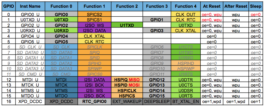
SDA --> GPIO04
SCK --> GPIO05
MOSI --> GPIO08
MISO --> GPIO06

Us that possible? How?

IRQ --> NC
GND --> GND
RST --> GPIO0
3.3V --> 3.3V

Re: Change default SPI pinouts?

PostPosted: Wed Apr 11, 2018 8:11 pm
by rudy
From page 10 of
https://media.readthedocs.org/pdf/ardui ... sp8266.pdf

SPI
SPI library supports the entire Arduino SPI API including transactions, including setting phase (CPHA). Setting the Clock polarity (CPOL) is not supported, yet (SPI_MODE2 and SPI_MODE3 not working).
The usual SPI pins are:

• MOSI = GPIO13
• MISO = GPIO12
• SCLK = GPIO14

There’s an extended mode where you can swap the normal pins to the SPI0 hardware pins. This is enabled by calling

SPI.pins(6, 7, 8, 0) before the call to SPI.begin(). The pins would change to:
• MOSI = SD1
• MISO = SD0
• SCLK = CLK
• HWCS = GPIO0

This mode shares the SPI pins with the controller that reads the program code from flash and is controlled by a hardware arbiter (the flash has always higher priority). For this mode the CS will be controlled by hardware as you can’t handle the CS line with a GPIO, you never actually know when the arbiter is going to grant you access to the bus so you must let it handle CS automatically.

Re: Change default SPI pinouts?

PostPosted: Wed Apr 11, 2018 8:36 pm
by nardev
rudy wrote:From page 10 of
https://media.readthedocs.org/pdf/ardui ... sp8266.pdf

SPI
SPI library supports the entire Arduino SPI API including transactions, including setting phase (CPHA). Setting the Clock polarity (CPOL) is not supported, yet (SPI_MODE2 and SPI_MODE3 not working).
The usual SPI pins are:

• MOSI = GPIO13
• MISO = GPIO12
• SCLK = GPIO14

There’s an extended mode where you can swap the normal pins to the SPI0 hardware pins. This is enabled by calling

SPI.pins(6, 7, 8, 0) before the call to SPI.begin(). The pins would change to:
• MOSI = SD1
• MISO = SD0
• SCLK = CLK
• HWCS = GPIO0

This mode shares the SPI pins with the controller that reads the program code from flash and is controlled by a hardware arbiter (the flash has always higher priority). For this mode the CS will be controlled by hardware as you can’t handle the CS line with a GPIO, you never actually know when the arbiter is going to grant you access to the bus so you must let it handle CS automatically.


Thank you very much.. i thought it's mroe on the software level so it's possible to swap any two pins in ESP .. like it's software supported for pwm or some other things..


thank you..

Re: Change default SPI pinouts?

PostPosted: Wed Apr 11, 2018 9:43 pm
by rudy
No, I don't think you can pick any pins you want. Those are specific pins that are the other option that can do SPI. I think it has to match one of these sets.

Image