
- Sun Dec 27, 2015 12:51 am
#37208
Copy of info for LUA...
1. Define used GPIO pin:
outpin=7 -- Select Triac Command pin - GPIO13
gpio.mode(outpin,gpio.OUTPUT)
gpio.write(outpin,gpio.LOW) -- Triac OFF
inpin=6 -- Zero crossing detector input - GPIO12
gpio.mode(inpin,gpio.INT,gpio.PULLUP) -- attach interrupt to ZCD
2. Zero Cross Detector function
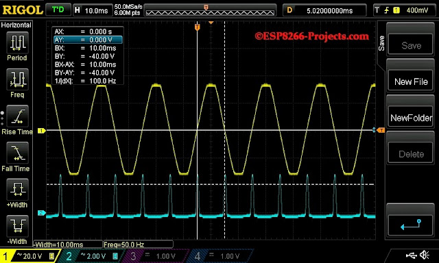
As you have seen above on the Osciloscope, zero crossing is the moment when the sinusoide goes through zero. After each zero crossing there is one full half of the sinuswave available to send through the Triac to the Load.
So what the software needs to do is to detect the zerocrossing, and then wait for a set amount of time on that sinuswave to switch on the TRIAC.
We have a 50Hz VAC that means is 50 waves per second.
Each sinuswave thus takes 1000ms/50=20ms
They are 2 sinus peaks in a wave. That means that after every zero crossing detection there is a 10ms period that we can regulate.
If we switch Triac directly at the beginning of that period, the load will receive full power
If we do it at the end of that 10ms period the load will receive none and if we do it halfway, the load will receive half power.
Now, how can we obtain the desired number of dimming steps?
If you look at the above explanation you know already the answer: we will divide the 10ms to the number of the steps we want and that's it. The obtained value can be tweaked a bit, depending on how is really looking your AC MAINS and how clean it is, filtering, delays, etc, but that's the dimming steps value you need to start with.
Let's assume we have:
Dimming steps = 128
Waveform Time= 10 ms
Step = 10000/128 = 78
Total dim time then is calculated as desired dimming steps * step value.
Also what we need to take in consideration after we fire the Triac is the Triac ON Propagation time (the time Triac needs to become fully ON).
function zero_cross()
dt = 76*dim
--print("Zero cross detected!")
stat = "ON"
tmr.delay(dt) -- Firing delay time calculated above
gpio.write(outpin,gpio.HIGH) -- Triac ON - Zero cross detected
tmr.delay(100) -- Triac ON - Propagation time
gpio.write(outpin,gpio.LOW) -- Triac OFF - let's be sure it's OFF before next cycle :)
tmr.wdclr()
return stat
end
3. Fading function for testing mode
function fading()
if(dim_up==1) then dim=dim+1
else dim=dim-1
end
if(dim < 10) then dim_up=1 dim=10
else if (dim > 120 ) then dim_up=0 dim=120
end
end
print("Dimmer level : " .. dim)
print("Fading mode : " .. dim_up)
tmr.wdclr()
end
4. Main code
dim = 120 -- Dimmer level - smaller value is brighter
dim_up=0 -- Fading direction - for test run
gpio.trig(inpin,"up",zero_cross) -- ZCD interrupt attached - trigger on falling edge
tmr.alarm(0, 100, 1, function() fading() end) --timer for testing mode
For testing, just save the code on ESP as 'dimmer.lua', restart ESP and run:
dofile("dimmer.lua") -- Start the Dimmer Testing mode
If you want the MPDMv3 software to start automatically when your CBDB module starts or reboots, then you neet to create and add some lines in your 'init.lua' file:
dofile("dimmer.lua") -- Start the Dimmer Testing mode
Save the code on ESP as 'init.lua', restart ESP. It should reboot and restart automatically the program.
1. Define used GPIO pin:
outpin=7 -- Select Triac Command pin - GPIO13
gpio.mode(outpin,gpio.OUTPUT)
gpio.write(outpin,gpio.LOW) -- Triac OFF
inpin=6 -- Zero crossing detector input - GPIO12
gpio.mode(inpin,gpio.INT,gpio.PULLUP) -- attach interrupt to ZCD
2. Zero Cross Detector function
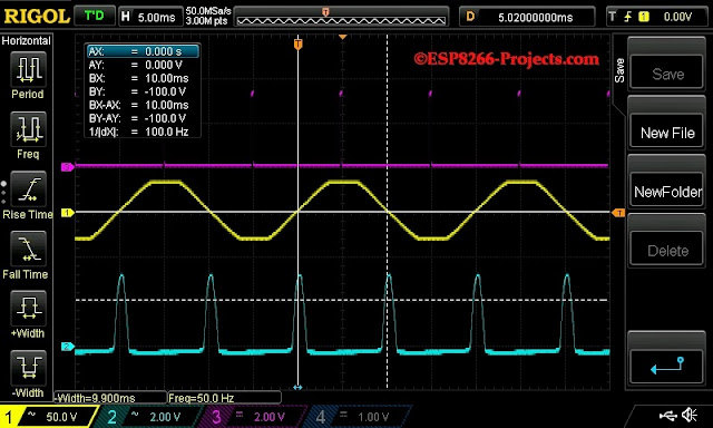
As you have seen above on the Osciloscope, zero crossing is the moment when the sinusoide goes through zero. After each zero crossing there is one full half of the sinuswave available to send through the Triac to the Load.
So what the software needs to do is to detect the zerocrossing, and then wait for a set amount of time on that sinuswave to switch on the TRIAC.
We have a 50Hz VAC that means is 50 waves per second.
Each sinuswave thus takes 1000ms/50=20ms
They are 2 sinus peaks in a wave. That means that after every zero crossing detection there is a 10ms period that we can regulate.
If we switch Triac directly at the beginning of that period, the load will receive full power
If we do it at the end of that 10ms period the load will receive none and if we do it halfway, the load will receive half power.
Now, how can we obtain the desired number of dimming steps?
If you look at the above explanation you know already the answer: we will divide the 10ms to the number of the steps we want and that's it. The obtained value can be tweaked a bit, depending on how is really looking your AC MAINS and how clean it is, filtering, delays, etc, but that's the dimming steps value you need to start with.
Let's assume we have:
Dimming steps = 128
Waveform Time= 10 ms
Step = 10000/128 = 78
Total dim time then is calculated as desired dimming steps * step value.
Also what we need to take in consideration after we fire the Triac is the Triac ON Propagation time (the time Triac needs to become fully ON).
function zero_cross()
dt = 76*dim
--print("Zero cross detected!")
stat = "ON"
tmr.delay(dt) -- Firing delay time calculated above
gpio.write(outpin,gpio.HIGH) -- Triac ON - Zero cross detected
tmr.delay(100) -- Triac ON - Propagation time
gpio.write(outpin,gpio.LOW) -- Triac OFF - let's be sure it's OFF before next cycle :)
tmr.wdclr()
return stat
end
3. Fading function for testing mode
function fading()
if(dim_up==1) then dim=dim+1
else dim=dim-1
end
if(dim < 10) then dim_up=1 dim=10
else if (dim > 120 ) then dim_up=0 dim=120
end
end
print("Dimmer level : " .. dim)
print("Fading mode : " .. dim_up)
tmr.wdclr()
end
4. Main code
dim = 120 -- Dimmer level - smaller value is brighter
dim_up=0 -- Fading direction - for test run
gpio.trig(inpin,"up",zero_cross) -- ZCD interrupt attached - trigger on falling edge
tmr.alarm(0, 100, 1, function() fading() end) --timer for testing mode
For testing, just save the code on ESP as 'dimmer.lua', restart ESP and run:
dofile("dimmer.lua") -- Start the Dimmer Testing mode
If you want the MPDMv3 software to start automatically when your CBDB module starts or reboots, then you neet to create and add some lines in your 'init.lua' file:
dofile("dimmer.lua") -- Start the Dimmer Testing mode
Save the code on ESP as 'init.lua', restart ESP. It should reboot and restart automatically the program.
Helpful? Donate To help support Mike http://www.esp8266basic.com click the donate button lets keep this project going and hope we can get the ESP32 in the mix. BEGINNERS GUIDE HERE http://www.esp8266.com/viewtopic.php?f=40&t=6732
Where I buy my ESP8266 boards from... (Banggood)
Where I buy my ESP8266 boards from... (Banggood)


