- Fri Nov 04, 2016 11:43 am
#57657
I had been playing with a bunch of ESP-01 boards, having a fair degree of success once I got to grips with the more timer/event driven programming model. But I needed more I/O's - so I bought a bunch of ESP-12F's - which have "ai-thinker" printed on their metal cases.
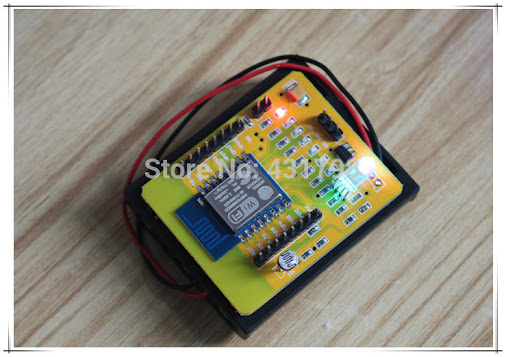
I wired up an 8 pin connector so I could plug my ESP-12F into the same socket that I'd been using to flash and test the ESP-01's. With that harness, I can flash the memory, run programs, and do *ALMOST* everything I can do with the ESP-01. Most things work identically...but not all...which is worrying.
Using my existing (native) code, I can probe the ROM software - and ask what version it is. The ESP12F claims to have "boot-version" 5 - where the ESP-01 has "boot-version" 6.
I don't think this can be re-written. It's not flash memory - it's ROM...right?
There are other differences too. The simplest "blink the TX LED" code doesn't work on the '12F'...even if I recode it to write directly to the I/O port registers! Yet the LED does flash when I flash it (for example).
Also when I run code to access my WiFi router and serve some HTML files - which is working just great on the ESP-01, it doesn't run worth a damn on the 12F module.
Other things (reading and writing the serial port, for example) work just fine.
It's confusing because there are so many subtly different ESP modules - but clearly they aren't remotely identical...which is going to make matters harder in the future.