Chat freely about anything...

User avatar
By bnvs
#14191 Okay guys I am work with the ESP8266 Dev Board the white one. This has the esp-201(esp201) chipset. I have the NodeMCU 0.95 integer firmware on the board. shown in this link Image

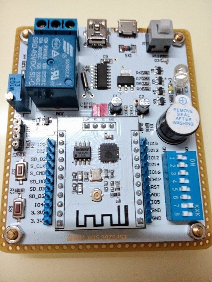
I am trying to write a small program BLINK program to turn the Red LED on and off. But I cannot seem to figure that out because of the gpio pins are off from what I found on the internet. I see the reference pinout from internet here.
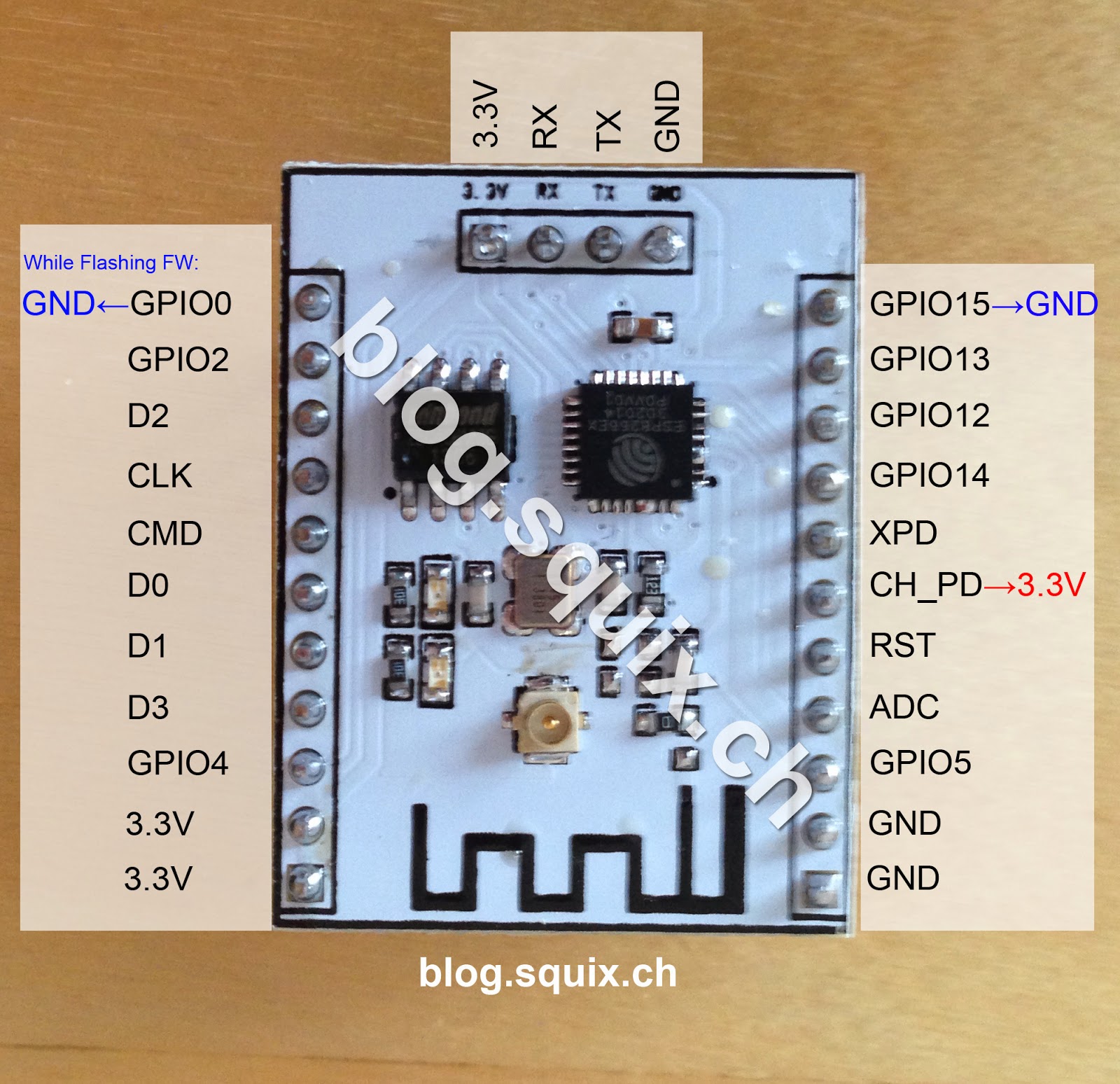
Imagealso here
Image

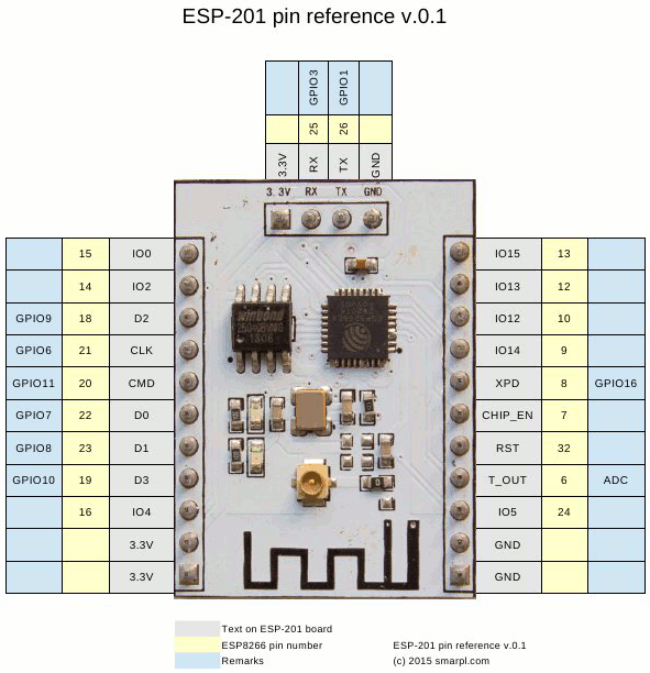
But the GPIO's above seem to be different to what I see from the output I got from Lua Uploader code below. I only see 0-12 GPIO's . Is there a different mapping or something with NodeMCU?

Code: Select allprint(gpio.read(0))
0
> print(gpio.read(1))
1
> print(gpio.read(2))
1
> print(gpio.read(3))
1
> print(gpio.read(4))
0
> print(gpio.read(5))
0
> print(gpio.read(6))
0
> print(gpio.read(7))
0
> print(gpio.read(8))
0
> print(gpio.read(9))
0
> print(gpio.read(10))
0
> print(gpio.read(12))
0
> print(gpio.read(13))
stdin:1: gpio 13 does not exist
> print(gpio.read(14))
stdin:1: gpio 14 does not exist
> print(gpio.read(15))
stdin:1: gpio 15 does not exist
> print(gpio.read(16))
stdin:1: gpio 16 does not exist
> print(gpio.read(17))
stdin:1: gpio 17 does not exist


Any help is appreciate.

Also if anyone got reference code on how they got the BLINK program working with this SDK dev board. Please share it.

Thanks
User avatar
By Mikejstb
#14194 I just loaded nodemcu Lua back onto a -201 on that dev board - my favorite dev board these days.

the red part of the RGB led is connected to gpio15.
The dev board takes care of gpio15 so you don't have to explicitly ground it for things to work.
If you do ground it you can't light the red led.
The undocumented part is that you have to switch both position 1 ('R") of the dip switch as well as setting position 7 ("K1") to off.
I think maybe dip position 7 - labeled K1 - grounds gpio15?

When I first got these dev boards I made a little Lua sketch to listen for mqtt messages to hopefully turn all the LED's and the relay on and off.
Once I figured out the dip pos 1/7 combination I found that everything worked other than the relay.

Another strange thing I've found with this board is I could turn the relay on and off from LuaLoaders gpio control - but doing from the Lua program never works. The little green led near the relay flashes but doesn't stay on and no "click". Very strange.

I got a lot of very helpful info on this dev board here - thanks to this blogger!

http://myesp8266.blogspot.com/2015_03_01_archive.html
User avatar
By bnvs
#14283 Thanks for the info previous poster. However I dont think I was able to find the answer I was asking for on your blog. Maybe I need more info. The code on your page is based on a NodeMCU code? if so what do you use to upload it to the Dev chip? As mentioned on the first post I am having issues knowing which GPIO pins translates to what component on the board.

My main questions is from a perspective of making a very simple blink program, what would that looks like? If you can help me here it would be great. I am sure others noobs like me would benefit as well.

So what is the GPIO pin assignment that I can use that would for say turning the White LED - ON/OFF for example? Or use another port as INPUT to drive the Relay port to turn on and off. (eg. when u turn on the Blue LED, the Relay port also goes on)

I am able to do the following on the board...but this does nothing to any components except for making the gpio pins go HIGH and LOW

Code: Select allprint(gpio.read(0))
gpio.mode(0, gpio.OUTPUT)
gpio.write(0, gpio.HIGH)
print(gpio.read(0))
gpio.write(0, gpio.LOW)
print(gpio.read(0))


And here is the output that it give me..

Code: Select allprint(gpio.read(0))
0
> gpio.write(0, gpio.HIGH)
> print(gpio.read(0))
1
> gpio.write(0, gpio.LOW)
> print(gpio.read(0))
0


This is all great but without knowing which GPIO pin does what and connected to where, whats the point? Please help.
User avatar
By Mikejstb
#14291 OK - I see the question better now.
Have a look at the nodemcu Lua documentation here
https://github.com/nodemcu/nodemcu-firmware/wiki/nodemcu_api_en
where you'll find a gpio map definition.

I also recommend that you use LuaLoader. It has a gpio section where you can manipulate any of the gpio pins where it also lets you see how the gpio numbers map to the I/O pin numbers.