- Thu Nov 12, 2015 7:48 am
#33772
I also miss-read that as GPIO15 shorted to 0V, thanks for pointing that out, my befuddled brain was mistakenly assuming the lettering applied to the adjacent pads on the module, as well as the pins going to the outside world. It is obvious from the pictures below, this is not the case and makes perfect sense.
I have some low standby current LDO voltage regulators on their way, so I can remove the 000 ohm link and put a regulator on the board. This might help avoid my original mistake of connecting VCC from my 3V3 FTDI adapter to the module and cooking it. (It appears that a genuine FTDI 3V3 cable has VCC at 5V... not 3V3 ooops. I should always check, never assume).
I'm also going to add any additional pullup/down resistors directly to the pins on the white PCB to keep the over all size as small as possible.
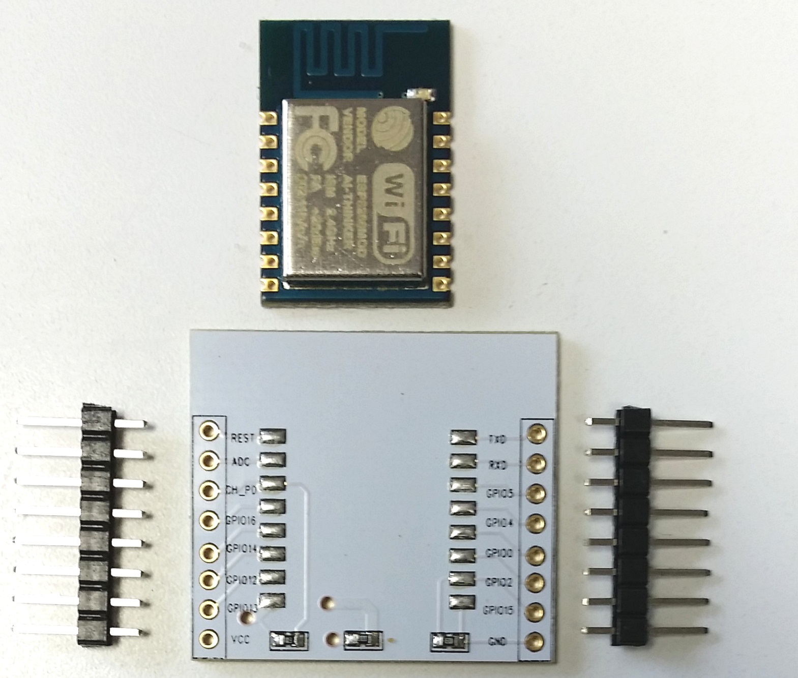
kenn wrote:I have a few of these. Look VERY closely at the traces.
The resistor on the left is 10k pullup on CH_PD. The resistor on the right is 10k pulldown on GPIO15, not GPIO2. This board has no resistor connected to GPIO2. the center "resistor" is 0 ohms - yes it's a jumper for when there isn't a 3.3v regulator added to the underside.
I add pullups to RESET and GPIO2 on the breadboard or board I plug into.
They're a nice little board - kind of wide for one breadboard - but a great adaptor for prototyping on 0.1" perfboard.
I also miss-read that as GPIO15 shorted to 0V, thanks for pointing that out, my befuddled brain was mistakenly assuming the lettering applied to the adjacent pads on the module, as well as the pins going to the outside world. It is obvious from the pictures below, this is not the case and makes perfect sense.
I have some low standby current LDO voltage regulators on their way, so I can remove the 000 ohm link and put a regulator on the board. This might help avoid my original mistake of connecting VCC from my 3V3 FTDI adapter to the module and cooking it. (It appears that a genuine FTDI 3V3 cable has VCC at 5V... not 3V3 ooops. I should always check, never assume).
I'm also going to add any additional pullup/down resistors directly to the pins on the white PCB to keep the over all size as small as possible.