Chat freely about anything...

User avatar
By BillM
#82470 Hello everyone,

I made a PCB at first to control some DC load but I wanted to use it for a motorcycle ignition.

First I did not think about back emf generated by the primary of the coil so it burnt the ecu :(

Here is the schematic :

Image

Here on the right, P1 and P2 are connected to IRLZ44N MOSFET's.

When I see people having this problem, the mosfet burns and not the µC.

I tried to add a flyback diode between Source and Drain and I also tried to add the diodes like this circuit :

Image

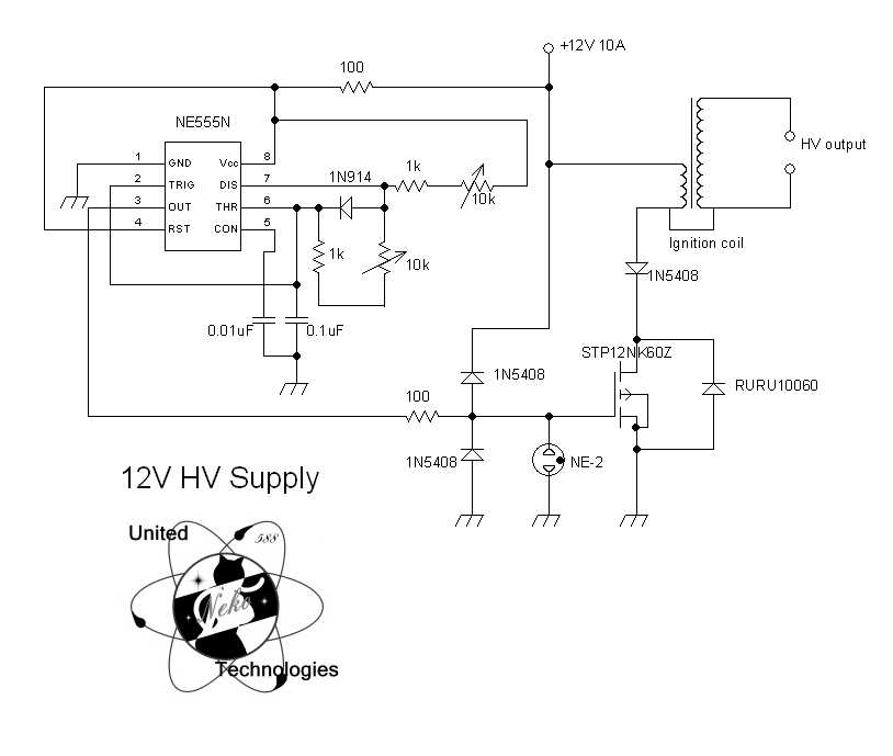
Instead of the 3 1N5408 I added 1N4001 (would this change something compared to 1N4007 just for the test ?)
and same for the RURU10060 I added an 1N4001

And ... Fried the ecu :evil: But at least there was a spark :lol:

I want to keep this as simple as it is (because PCB is already made).

Can you please help me first figure out what exactly burns the ecu (high voltage on gate ???) because I have no clue (I hate electromagnetic fields) and maybe tell me an efficient protection to this delicate µC ?

Thanks.
User avatar
By rudy
#82471 The schematic only shows what are connected and not how it is connected. Circuit board layout matters.

But since we only have your schematic to go on, I think a problem is spikes coming in through the power supply. If you have access to an oscilloscope take a look at the power input. Make sure the ground for the scope is connected at the regulator ground. But if you don't have a scope, then try this.

Put some filtering in line before the regulator input. An LC network.

Now haven looked more closely at your schematic, where is the capacitors at the input to the regulator? Please tell me you just forgot to put them on the schematic, but they are on the board.

Looking at the other circuit you included. They used diodes on the gate to clamp spikes. I think that was a bad choice of the type of diode. I would have used faster reacting ones. But is looks like the neon bulb is being used as a initial clamp for the edge. Considering at what voltage it will fire, I don't think it is a good method to use.

But the use of some fast diodes is worth trying. I would look at that as well as a surge suppressor "transorb". And transorbs on the input of the regulator is a good idea as well.

But all of this working is dependent on proper implementation. How well you have routed things.
User avatar
By BillM
#82476 Ok, here is my circuit layout. This is the first circuit I ever created.

Image

So you think that high voltage is coming through the power supply to the regulator and then burns the controller ? How does that work ?

What causes that ? If I get it, the LC network before the input should absorb the high power during the spark ?

And yes I forgot the capacitance at the input. What is the role of the capacitor here ? Sould it be a ceramic one like at the output ?
User avatar
By rudy
#82482 Keep high power circuits away from low power sensitive circuits. You have your connectors on one side and the switching devices on the other side. My guess is that you wanted the mosfets to be on a heatsink, therefor you put them on a clear side of the board. I would have found a better way if that was the case.

You are energizing a coil and on the release you are intentionally causing a high voltage flyback pulse. You need to keep this out of, and away from, the control electronics. Put the nasty stuff on one side of the board and the sensitive stuff on the opposite side.

The second schematic you showed, there is a 100 Ohm resistor that is used to separate the power for the chip and the raw power. The NE555 does not require much current to operate so a series resistor does not limit the current much. There should be a capacitor from Vcc to gnd.

Your circuit requires a lot more current. You can't put resistance in series with the power supply. But you can put inductance in series. Low resistance to DC current, but high impedance to higher frequency waveforms. What you want to do is provide high frequency filtering. Blocking the waveform with the choke and filtering with a capacitor.

If I get it, the LC network before the input should absorb the high power during the spark ?


The inductor/choke blocks the pulse and the capacitor provides a low impedance path on the protected side.
https://en.wikipedia.org/wiki/Choke_(electronics)
http://electriciantraining.tpub.com/141 ... er-196.htm

What is the role of the capacitor here?

It provide a low impedance reservoir for the regulator and most regulators need it in order to be stable.

It seems like you didn't do any serious research. What you are trying to accomplish is not trivial. In order to make a reliable functional design require a good understanding of the design issues of the application.