- Fri Mar 27, 2020 5:58 pm
#86216
HI guys,
I want some advice before making something stupid
I want to create a simple solar watering system with a small water pump.
Basically I will have those components, please tell me if it will work without burning my house.

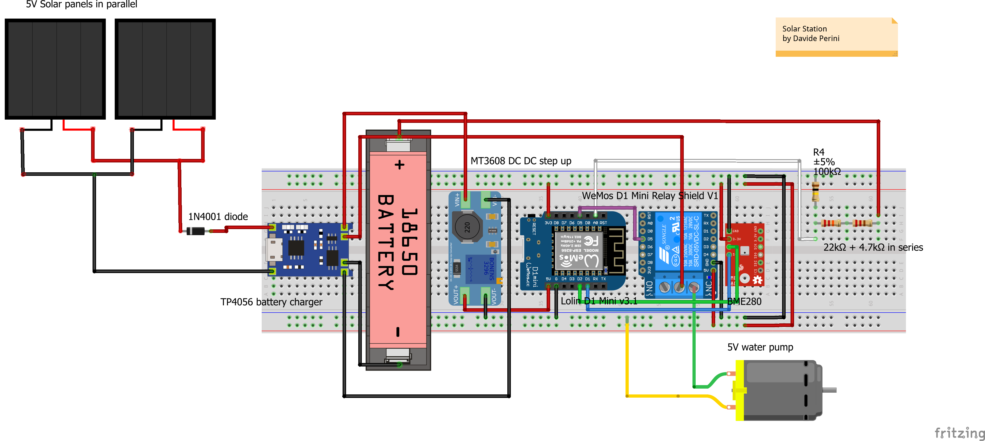
As you can see from the image I have two 5V solar panels in parallel
connected to the TP4056 battery charger with a 1N4001 diode to avoid back current.
The battery is connected to the TP4056 charger and to the MT3608 DC-DC Step Up Module.
The MT3608 DC-DC Step Up Module powers the ESP8266 microcontroller via VIN directly.
To the ESP microcontroller I attached a relay shield that will drive the water pump, the water pump is directly connected to the 18650 lithium battery.
I attached a BME280 temp sensor to the ESP.
I will use deep sleep on the ESP8266 and it will be turned on every 10 minutes to send temperatures via MQTT. Once a day it will power the pump for about 15 seconds to give some water to a plant.
Does this have sense? Can it work? Do you see some problems?
I want some advice before making something stupid
I want to create a simple solar watering system with a small water pump.
Basically I will have those components, please tell me if it will work without burning my house.
As you can see from the image I have two 5V solar panels in parallel
connected to the TP4056 battery charger with a 1N4001 diode to avoid back current.
The battery is connected to the TP4056 charger and to the MT3608 DC-DC Step Up Module.
The MT3608 DC-DC Step Up Module powers the ESP8266 microcontroller via VIN directly.
To the ESP microcontroller I attached a relay shield that will drive the water pump, the water pump is directly connected to the 18650 lithium battery.
I attached a BME280 temp sensor to the ESP.
I will use deep sleep on the ESP8266 and it will be turned on every 10 minutes to send temperatures via MQTT. Once a day it will power the pump for about 15 seconds to give some water to a plant.
Does this have sense? Can it work? Do you see some problems?