Table of Contents
Connecting the board
The ESP8266 runs on 3.3V and is NOT 5V TOLERANT, so you cannot just connect it to an Arduino. As the chip can draw up to 300mA when transmitting, you will need a good power supply. If in doubt, use a large capacitor (>100uf) to regulate the supply, near the chip. Failure to do so will result in instability.
Since the firmware is uploaded through the serial interface, you will typically use a USB to serial adapter. Here is the one I use:
Make sure you get one that works at 3V or with a 3V/5V switch, like this one.
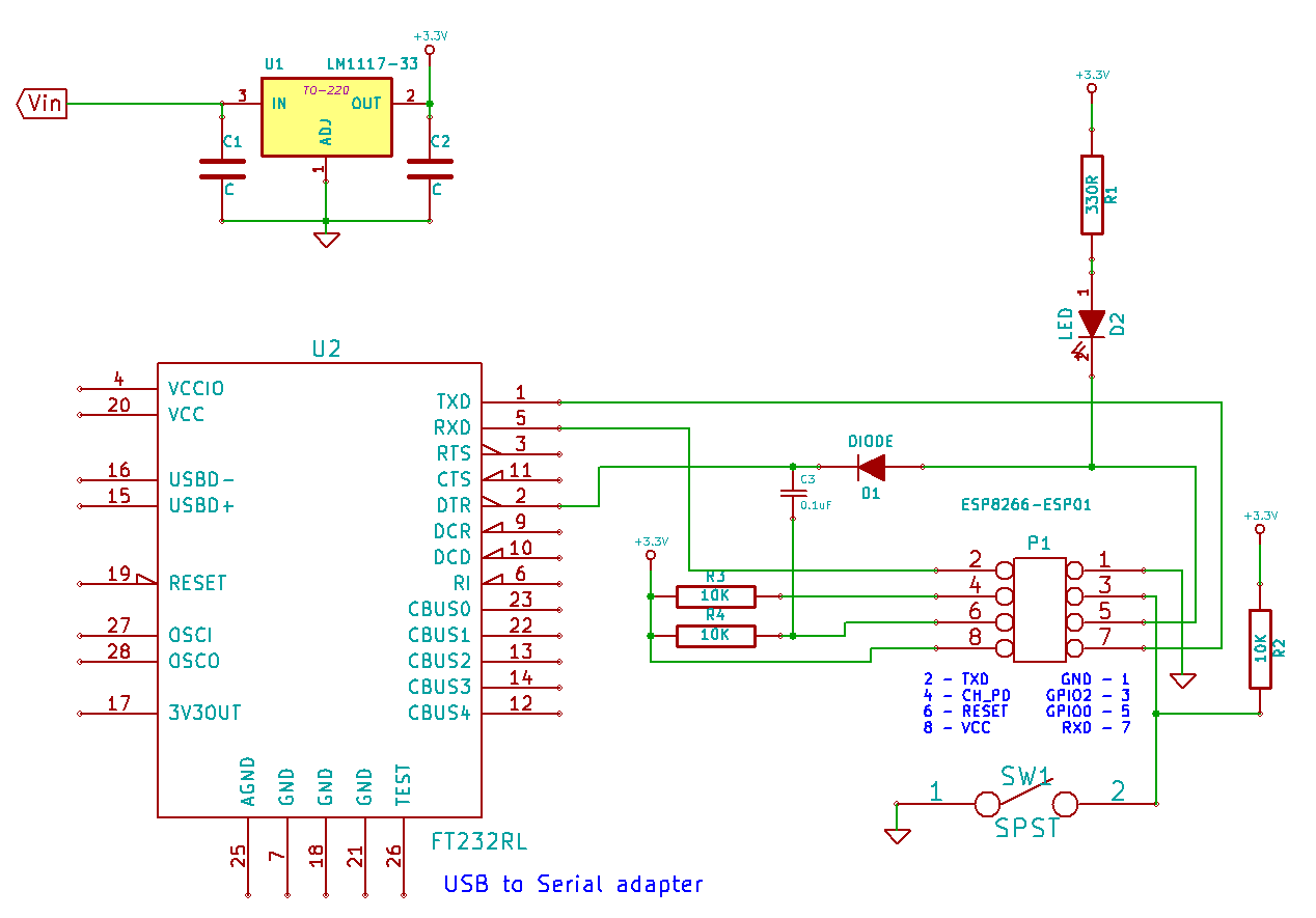 ESP-01 Hardware connections
To get the chip into firmware update mode, the chip needs to be reset while GPIO0 is held low and GPIO2 is held high. The above circuit uses the USB-serial adapter's DTR line to pull GPIO0 low and reset the chip via a small capacitor. GPIO0 needs to be held down for about 15ms after reset for the chip to go into firmware update mode. After that, GPIO0 needs to be released, as the bootloader then reconfigures GPIO0 as an output. All of this is handled automatically by the flash tool.