Table of Contents
Modules
Most common modules ESP-NN seem to come from AI-Thinkers vendor. Espressif Systems themselves have produced the ESP-WROOM-02 Wi-Fi Module.
All Modules by AI-Thinker : see http://wiki.ai-thinker.com/_media/esp8266/esp8266_module_list.png
- 推荐型号 (Green) : Recommended Model
- 停产型号 (Gray) : Discontinued Model
Product Specification : http://wiki.ai-thinker.com/esp8266/docs
User Manual : http://wiki.ai-thinker.com/_media/esp8266/a000um01a3.pdf
There are also modules from other vendors, such as :
- Olimex, see https://www.olimex.com/Products/IoT/,
- Wireless-tag, see http://www.wireless-tag.com/index.php/Product/dis/33.html
- Qilianer, see http://en.qilianer.com/product/28032.html
- Smarttime.cn, see http://www.smartline.com.cn/
and other unknown vendors are starting to become available.
Apparently new versions of older modules are appearing with larger flash sizes. To check the flash size of your module:
# esptool.py –port /dev/ttyUSB0 –baud 115200 flash_id- Connecting…
- Manufacturer: c8
- Device: 4013
Then check out the combo at https://code.coreboot.org/p/flashrom/source/tree/HEAD/trunk/flashchips.h:
- manufacturer c8 is GigaDevice and device 4013 is GD25Q40, which is a 4Mbit=512KByte device
- manufacturer ef is Winbond (ex Nexcom) and device 4016 is W25Q32, which is a 32Mbit=4MByte device
ESP-WROOM-02 By Espressif Systems

CE of ESP-WROOM-02

FCC of ESP-WROOM-02

ESP-01
Note: Some batches of this module ship with LED Current limiting resistors of the wrong value (47Ohm vs 4.7KOhm). This usually results in the power LED vanishing in a puff of smoke.


ESP-02


ESP-03


| Pin | Name | Alternate Functions | Notes |
|---|---|---|---|
| 1 | GND | (Pin 1 is in the corner close to the crystal and away from antenna) | |
| 2 | NC | ||
| 3 | UTXD | SPICS1, GPIO1, CLK_RTC | Typically used as serial uart0 TX |
| 4 | URXD | I2SO_DATA, GPIO3, CLK_XTAL | Typically used as serial uart0 RX |
| 5 | GPIO16 | XPD_DCDC, RTC_GPIO0, EXT_WAKEUP, DEEPSLEEP | Connected to XPD_DCDC ESP pin, can also be connected to ESP EXT_RSTB (reset) pin by closing jumper near pin 8; Reset pin is active low and has an internal weak pull-up; Connecting jumper is required to wake-up ESP from deep-sleep: RTC produces pulse on XPD_DCDC pin that needs to be fed into EXT_RSTB pin |
| 6 | CH_PD | Power-down: low input powers down chip, high powers up; tie high for normal operation or module will not function | |
| 7 | ANT | Wifi Antenna, do not connect | |
| 8 | VCC | 3.3V input (pin 8 is between antenna and ESP chip) | |
| 9 | GPIO14 | MTMS, I2SI_WS, SP_CLK | |
| 10 | GPIO12 | MTDI, I2SI_DATA, MISO | |
| 11 | GPIO13 | MTCK, I2SI_BCK, MOSI | |
| 12 | GPIO15 | MTDO, I2SO_BCK, SP_CS | At boot: must be low to enter flash or normal boot (high enters special boot modes) |
| 13 | GPIO2 | I2SO_WS, U1TXD, U0TXD | At boot: must be high to enter flash or normal boot (low enters special boot modes); Typically is used as uart1 TX for debug logging |
| 14 | GPIO0 | SPICS2, CLK_OUT | At boot: low causes bootloader to enter flash upload mode; high causes normal boot |
ESP-04


ESP-05


ESP-06


![]() not FCC approved (*)
not FCC approved (*) ![]()


ESP-07


Note: some versions have an error on silkscreen: GPIO4 and GPIO5 are exchanged!
![]() not FCC approved (*)
not FCC approved (*) ![]()
 under the can by Baoshi

 pinout of current 16 pin variant

![]() pinout shows early 14 pin variant
pinout shows early 14 pin variant
Notable difference between 14 and 16 pins variants is that 16 pins has LEDs outside shield. Also, antenna socket is on the bottom left, whereas 14-pin has antenna on the top left.
ESP-08


![]() not FCC approved (*)
not FCC approved (*) ![]()

Two versions of ESP-08 are on the market: one with 7×2 pins (like the one in the picture) and probably a new one with 8×2+ant pins (pinout is the same like the new 8×2 ESP-07)

ESP-09


ESP-10


ESP-11


ESP-12


![]() not FCC approved(*)
not FCC approved(*) ![]()
(*) not FCC approved, just labelled to look like they do, not a valid FCC ID on the label
FCC of ESP-12
FCC ID: 2ADUIESP-12


CE of ESP-12
CE NUMBER: BCTC-141212468

Note:This is not an EU CE declaration of conformity, This is a test pass certificate from a third party test company that has no official standing. An official EU DoC must be made by the manufacturer not a third party. Also note safety standard EN60950 does not exist, and has not for many many years. The R&TTE directive quoted ceased to be valid in 2016. These comments and similar apply to a lot of the certificates on this page.
ESP-12F

ESP-12-E/Q


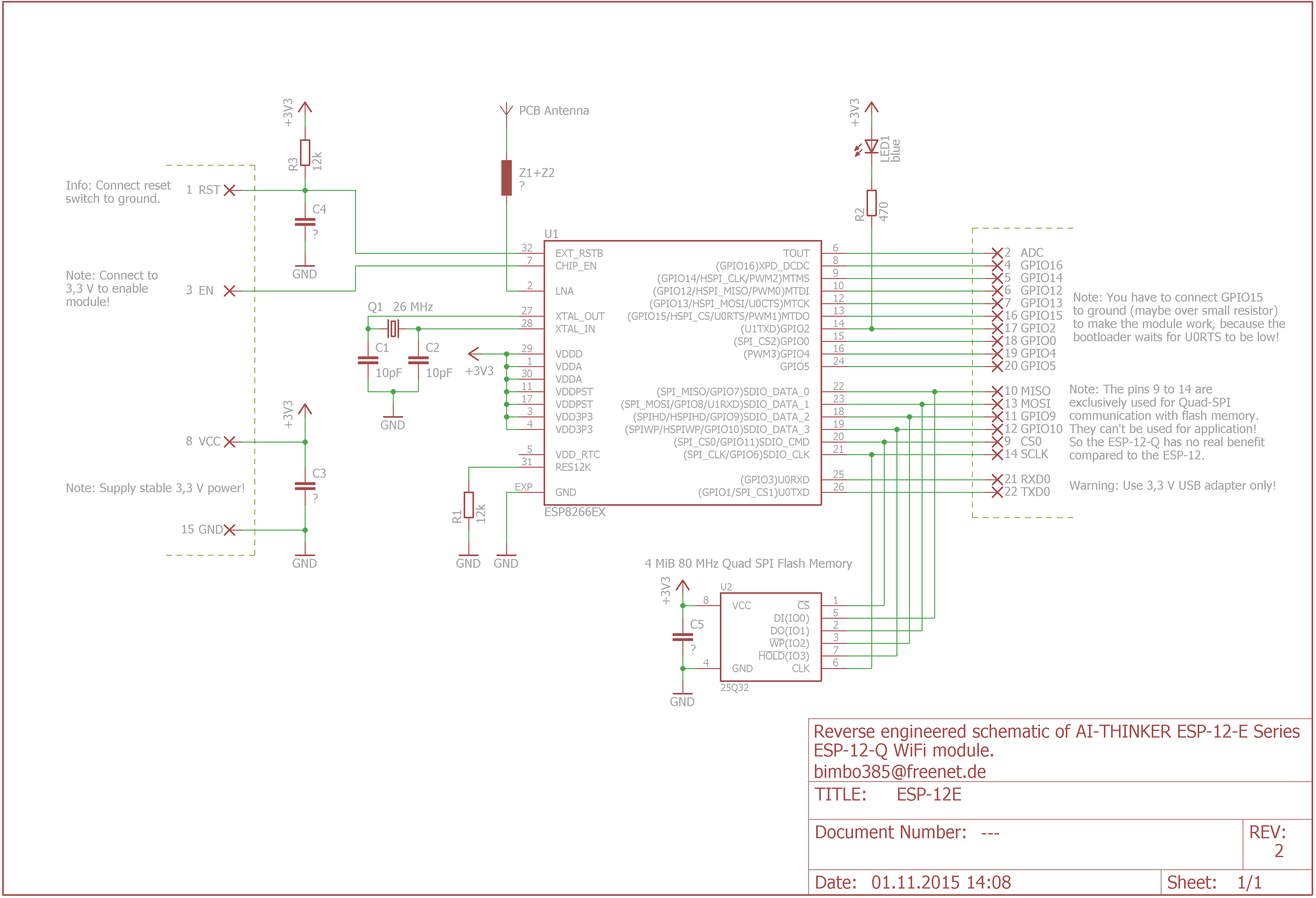
![]() This reverse engineered schematic wrong in flash connection. Check table below
This reverse engineered schematic wrong in flash connection. Check table below ![]()
FLASH SDIO
| ESP Pin | Func | Alternate Functions | Flash pin | Err by bimbo385 |
|---|---|---|---|---|
| 18 | SDIO_DATA_2 | [SPIHD] | pin 7 [!HOLD] | 3(!WP [IO2]) |
| 19 | SDIO_DATA_3 | [SPIWP] | pin 3 [!WP] | 7(!HOLD [IO3]) |
| 20 | SDIO_CMD | [SDIO_CMD] | pin 1 [!CS] | |
| 21 | SDIO_CLK | [SPICLK] | pin 6 [CLK] | |
| 22 | SDIO_DATA_0 | [SPIQ/MISO] | pin 2 [DO] | 5 (DI [IO0]) |
| 23 | SDIO_DATA_1 | [SPID/MOSI] | pin 5 [DI] | 2 (DO [IO1]) |
 Please, fix this table if it possible.
ESP-12S

ESP-13

ESP-14
 The etching on the shield reads: 'STM8S003 INSIDE'
 Backside of the ESP8266-14 module.
The ESP8266-14 module has pins and connections on three sides of the board
Backside of the ESP8266-14 module.
The ESP8266-14 module has pins and connections on three sides of the board
 ESP8266-14 module with metal shield removed. Underneath the shield there is a 20-pin QFPN chip with the marking 'S033', which according to the STM8S003 datasheet is the proper device marking.
WT8266-S1 By Wireless-Tag

CE of WT8266-S1

FCC of WT8266-S1

Modules Family


Modules shown here together with an external aerial, a large, cheap and poor quality development board together with a small, expensive and high quality development board.
Summary Table
| Board ID | #Pins | Pitch | Form factor | LEDs | Antenna | Ant.Socket | Shielded | Dimensions mm | Flash Size in Bytes and (bits) |
|---|---|---|---|---|---|---|---|---|---|
| ESP-01 | 8 | 0.1“ | 2×4 DIL | Yes | Etched-on PCB | No | No | 14.3 x 24.8 | 512KB (4Mb) ×× |
| ESP-02 | 8 | 0.1” | 2×4 notch | No? | None | Yes | No | 14.2 x 14.2 | 512KB (4Mb) × |
| ESP-03 | 14 | 2mm | 2×7 notch | No | Ceramic | No | No | 17.3 x 12.1 | 512KB (4Mb) × |
| ESP-04 | 14 | 2mm | 2×4 notch | No? | None | No | No | 14.7 x 12.1 | 512KB (4Mb) × |
| ESP-05 | 5 | 0.1“ | 1×5 SIL | No | None | Yes | No | 14.2 x 14.2 | 512KB (4Mb) × |
| ESP-06 | 12+GND | misc | 4×3 dice | No | None | No | Yes | 16.3 x 13.1 | 512KB (4Mb) × |
| ESP-07 | 16 | 2mm | 2×8 pinhole | Yes | Ceramic | Yes | Yes | 21.2 x 16.0 | 1MB (8Mb) ×× |
| ESP-07S | 16 | 2mm | 2×8 pinhole | No | None | Yes | Yes | 17.0 x 16.0 | 4MB (32Mb) |
| ESP-08 | 14 | 2mm | 2×7 notch | No | None | No | Yes | 17.0 x 16.0 | ?? (please fill if you know) |
| ESP-08 New | 16 | 2mm | 2×8 notch | No | None | No | Yes | 18.0 x 16.0 | ?? (please fill if you know) |
| ESP-09 | 12+GND | misc | 4×3 dice | No | None | No | No | 10.0 x 10.0 | 1MB (8Mb) |
| ESP-10 | 5 | 2mm ?? | 1×5 notch | No | None | No | No | 14.2 x 10.0 | 512KB (4Mb) * |
| ESP-11 | 8 | 1.27mm | 1×8 pinhole | No? | Ceramic | No | No | 17.3 x 12.1 | 512KB (4Mb) * |
| ESP-12 | 16 | 2mm | 2×8 notch | Yes | Etched-on PCB | No | Yes | 24.0 x 16.0 | 4MB (32Mb) ?? |
| ESP-12F | 22 | 2mm | 2×8 notch | Yes | Etched-on PCB | No | Yes | 24.0 x 16.0 | 4MB (32Mb) |
| ESP-12E | 22 | 2mm | 2×8 notch | Yes | Etched-on PCB | No | Yes | 24.0 x 16.0 | 4MB (32Mb) |
| ESP-12S | 16 | 2mm | 2×8 notch | Yes | Etched-on PCB | No | Yes | 24.0 x 16.0 | 4MB (32Mb) |
| ESP-13 | 18 | 1.5mm | 2×9 | ? | Etched-on PCB | No | Yes | 20.0 x 19.9 | 4MB (32Mb) |
| ESP-14 | 22 | 2mm | 2×8 + 6 | 1 | Etched-on PCB | No | Yes | 24.3 x 16.2 | ?? (please fill if you know) |
| ESP-201 | 22+4 | 0.1” | 2×11 + 4 | 2 | Etched-on PCB ××× | Yes | No | 33.5 x 25.5 | 512KB (4Mb) |
| WROOM-02 | 18 | 1.5mm | 2×9 | No | Etched on PCB | No | Yes | 20.0 x 18.0 | ?? (please fill if you know) |
| WT8266-S1 | 18 | 1.5mm | 3×6 | 1 | Etched on PCB | No | Yes | 15.0 x 18.6 | 4MB (32Mb) |
× New firmwares can only be flashed on boards with at least 1MB (8Mb) flash. ×× May be different on different editions of the board. ××× Antenna connector is connected by default, to use PCB antenna switch (solder) the 0Ω resistor to the corresponding position.
more products : http://wiki.ai-thinker.com/_media/esp8266/esp8266_module_list.png