ota-over-the-air-esp8266
Differences
This shows you the differences between two versions of the page.
| Next revision | Previous revision | ||
|
ota-over-the-air-esp8266 [2016/06/15 15:22] admin created |
ota-over-the-air-esp8266 [2016/06/15 15:41] admin |
||
|---|---|---|---|
| Line 1: | Line 1: | ||
| - | --- | + | ====== Over The Air Updates ESP8266 (OTA) ====== |
| - | title: OTA Update | + | |
| - | --- | + | |
| ## Table of Contents | ## Table of Contents | ||
| Line 116: | Line 114: | ||
| **Note:** Windows users should select “Add python.exe to Path” (see below – this option is not selected by default). | **Note:** Windows users should select “Add python.exe to Path” (see below – this option is not selected by default). | ||
| - |  | + |  |
| 2. Now prepare the sketch and configuration for the upload over a serial port. | 2. Now prepare the sketch and configuration for the upload over a serial port. | ||
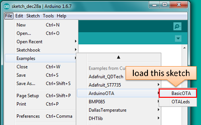
| - Start Arduino IDE and load sketch BasicOTA.ino available under File > Examples > ArduinoOTA | - Start Arduino IDE and load sketch BasicOTA.ino available under File > Examples > ArduinoOTA | ||
| - |  | + |  |
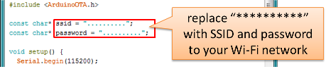
| - Update SSID and password in the sketch so the module can join your Wi-Fi network | - Update SSID and password in the sketch so the module can join your Wi-Fi network | ||
| - |  | + |  |
| | | ||
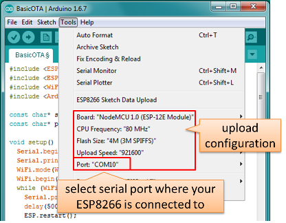
| - Configure upload parameters as below (you may need to adjust configuration if you are using a different module): | - Configure upload parameters as below (you may need to adjust configuration if you are using a different module): | ||
| - |  | + |  |
| **Note:** Depending on version of platform package and board you have, you may see ``` Upload Using: ``` in the menu above. This option is inactive and it does not matter what you select. It has been left for compatibility with older implementation of OTA and is targeted for removal in platform package version 2.2.0. | **Note:** Depending on version of platform package and board you have, you may see ``` Upload Using: ``` in the menu above. This option is inactive and it does not matter what you select. It has been left for compatibility with older implementation of OTA and is targeted for removal in platform package version 2.2.0. | ||
| Line 132: | Line 130: | ||
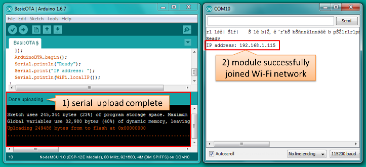
| 3. Upload the sketch (Ctrl+U). Once done, open Serial Monitor (Ctrl+Shift+M) and check if module has joined your Wi-Fi network: | 3. Upload the sketch (Ctrl+U). Once done, open Serial Monitor (Ctrl+Shift+M) and check if module has joined your Wi-Fi network: | ||
| - |  | + |  |
| 4. Only if module is connected to network, after a couple of seconds, the esp8266-ota port will show up in Arduino IDE. Select port with IP adress shown in Serial Monitor in previus step: | 4. Only if module is connected to network, after a couple of seconds, the esp8266-ota port will show up in Arduino IDE. Select port with IP adress shown in Serial Monitor in previus step: | ||
| - |  | + | 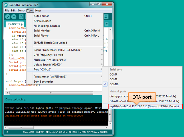 |
| | | ||
| **Note:** If OTA port does not show up, exit Arduino IDE, open it again and check if port is there. If it does not help check your firewall settings. | **Note:** If OTA port does not show up, exit Arduino IDE, open it again and check if port is there. If it does not help check your firewall settings. | ||
| Line 142: | Line 140: | ||
| 5. Now get ready for your first OTA upload by selecting the OTA port: | 5. Now get ready for your first OTA upload by selecting the OTA port: | ||
| - |  | + | 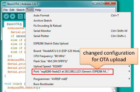 |
| | | ||
| **Note:** The menu entry ``` Upload Speed: ``` does not matter at this point as it concerns the serial port. Just left it unchanged. | **Note:** The menu entry ``` Upload Speed: ``` does not matter at this point as it concerns the serial port. Just left it unchanged. | ||
| Line 148: | Line 146: | ||
| 6. If you have successfully completed all the above steps, you can upload (Ctrl+U) the same (or any other) sketch over OTA: | 6. If you have successfully completed all the above steps, you can upload (Ctrl+U) the same (or any other) sketch over OTA: | ||
| - |  | + | 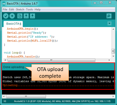 |
| **Note:** To be able to upload your sketch over and over again using OTA, you need to embed OTA routines inside. Please use BasicOTA.ino as an example. | **Note:** To be able to upload your sketch over and over again using OTA, you need to embed OTA routines inside. Please use BasicOTA.ino as an example. | ||
| Line 166: | Line 164: | ||
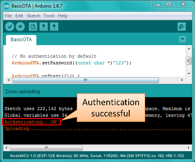
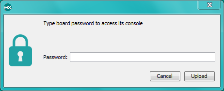
| Before implementing it in your sketch, it is a good idea to check how it works using *BasicOTA.ino* sketch available under *File > Examples > ArduinoOTA*. Go ahead, open *BasicOTA.ino*, uncomment the above statement that is already there, and upload the sketch. To make troubleshooting easier, do not modify example sketch besides what is absolutely required. This is including original simple ``` 123 ``` OTA password. Then attempt to upload sketch again (using OTA). After compilation is complete, once upload is about to begin, you should see prompt for password as follows: | Before implementing it in your sketch, it is a good idea to check how it works using *BasicOTA.ino* sketch available under *File > Examples > ArduinoOTA*. Go ahead, open *BasicOTA.ino*, uncomment the above statement that is already there, and upload the sketch. To make troubleshooting easier, do not modify example sketch besides what is absolutely required. This is including original simple ``` 123 ``` OTA password. Then attempt to upload sketch again (using OTA). After compilation is complete, once upload is about to begin, you should see prompt for password as follows: | ||
| - |  | + | 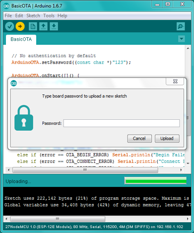 |
| Enter the password and upload should be initiated as usual with the only difference being ``` Authenticating...OK ``` message visible in upload log. | Enter the password and upload should be initiated as usual with the only difference being ``` Authenticating...OK ``` message visible in upload log. | ||
| - |  | + |  |
| You will not be prompted for a reentering the same password next time. Arduino IDE will remember it for you. You will see prompt for password only after reopening IDE, or if you change it in your sketch, upload the sketch and then try to upload it again. | You will not be prompted for a reentering the same password next time. Arduino IDE will remember it for you. You will see prompt for password only after reopening IDE, or if you change it in your sketch, upload the sketch and then try to upload it again. | ||
| Line 176: | Line 174: | ||
| Please note, it is possible to reveal password entered previously in Arduino IDE, if IDE has not been closed since last upload. This can be done by enabling *Show verbose output during: upload* in *File > Preferences* and attempting to upload the module. | Please note, it is possible to reveal password entered previously in Arduino IDE, if IDE has not been closed since last upload. This can be done by enabling *Show verbose output during: upload* in *File > Preferences* and attempting to upload the module. | ||
| - |  | + | 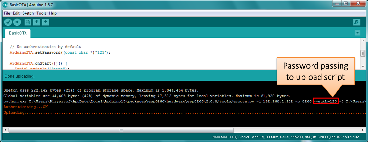 |
| The picture above shows that the password is visible in log as it is passed to *espota.py* upload script. | The picture above shows that the password is visible in log as it is passed to *espota.py* upload script. | ||
| Line 182: | Line 180: | ||
| Another example below shows situation when password is changed between uploads. | Another example below shows situation when password is changed between uploads. | ||
| - |  | + |  |
| When uploading, Arduino IDE used previously entered password, so the upload failed and that has been clearly reported by IDE. Only then IDE prompted for a new password. That was entered correctly and second attempt to upload has been successful. | When uploading, Arduino IDE used previously entered password, so the upload failed and that has been clearly reported by IDE. Only then IDE prompted for a new password. That was entered correctly and second attempt to upload has been successful. | ||
| Line 191: | Line 189: | ||
| If OTA update fails, first step is to check for error messages that may be shown in upload window of Arduino IDE. If this is not providing any useful hints try to upload again while checking what is shown by ESP on serial port. Serial Monitor from IDE will not be useful in that case. When attempting to open it, you will likely see the following: | If OTA update fails, first step is to check for error messages that may be shown in upload window of Arduino IDE. If this is not providing any useful hints try to upload again while checking what is shown by ESP on serial port. Serial Monitor from IDE will not be useful in that case. When attempting to open it, you will likely see the following: | ||
| - |  | + |  |
| This window is for Arduino Yún and not yet implemented for esp8266/Arduino. It shows up because IDE is attempting to open Serial Monitor using network port you have selected for OTA upload. | This window is for Arduino Yún and not yet implemented for esp8266/Arduino. It shows up because IDE is attempting to open Serial Monitor using network port you have selected for OTA upload. | ||
| Line 199: | Line 197: | ||
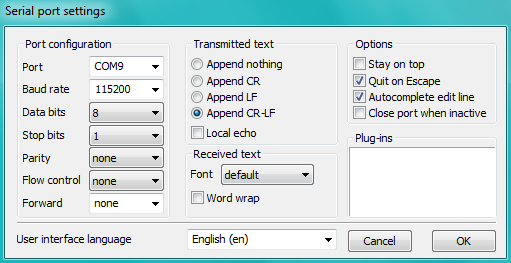
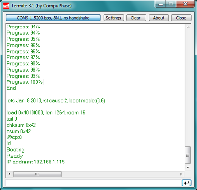
| Select COM port and baud rate on external terminal program as if you were using Arduino Serial Monitor. Please see typical settings for [Termite](http://www.compuphase.com/software_termite.htm) below: | Select COM port and baud rate on external terminal program as if you were using Arduino Serial Monitor. Please see typical settings for [Termite](http://www.compuphase.com/software_termite.htm) below: | ||
| - |  | + |  |
| Then run OTA from IDE and look what is displayed on terminal. Successful [ArduinoOTA](#arduinoota) process using BasicOTA.ino sketch looks like below (IP address depends on your network configuration): | Then run OTA from IDE and look what is displayed on terminal. Successful [ArduinoOTA](#arduinoota) process using BasicOTA.ino sketch looks like below (IP address depends on your network configuration): | ||
| - |  | + |  |
| If upload fails you will likely see errors caught by the uploader, exception and the stack dump, or both. | If upload fails you will likely see errors caught by the uploader, exception and the stack dump, or both. | ||
| Line 274: | Line 272: | ||
| - Open File > Preferences, look for “Show verbose output during:” and check out “compilation” option. | - Open File > Preferences, look for “Show verbose output during:” and check out “compilation” option. | ||
| - |  | + | 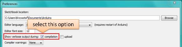 |
| **Note:** This setting will be required in step 5 below. You can uncheck this setting afterwards. | **Note:** This setting will be required in step 5 below. You can uncheck this setting afterwards. | ||
| Line 280: | Line 278: | ||
| 3. Upload sketch (Ctrl+U). Once done open Serial Monitor (Ctrl+Shift+M) and check if you see the following message displayed, that contains url for OTA update. | 3. Upload sketch (Ctrl+U). Once done open Serial Monitor (Ctrl+Shift+M) and check if you see the following message displayed, that contains url for OTA update. | ||
| - |  | + | 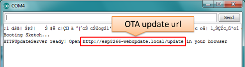 |
| **Note:** Such message will be shown only after module successfully joins network and is ready for an OTA upload. | **Note:** Such message will be shown only after module successfully joins network and is ready for an OTA upload. | ||
| Line 286: | Line 284: | ||
| 4. Now open web browser and enter the url provided on Serial Monitor, i.e. http://esp8266-webupdate.local/update. Once entered, browser should display a form like below that has been served by your module. The form invites you to choose a file for update. | 4. Now open web browser and enter the url provided on Serial Monitor, i.e. http://esp8266-webupdate.local/update. Once entered, browser should display a form like below that has been served by your module. The form invites you to choose a file for update. | ||
| - |  | + | 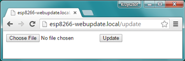 |
| | | ||
| **Note:** If entering ``` http://esp8266-webupdate.local/update ``` does not work, try replacing ``` esp8266-webupdate ``` with module’s IP address. For example, if your module IP is ``` 192.168.1.100 ``` then url should be ``` http://192.168.1.100/update ```. This workaround is useful in case the host software installed in step 2 does not work. If still nothing works and there are no clues on Serial Monitor, try to diagnose issue by opening provided url in Google Chrome, pressing F12 and checking contents of “Console” and “Network” tabs. Chrome provides some advanced logging on these tabs. | **Note:** If entering ``` http://esp8266-webupdate.local/update ``` does not work, try replacing ``` esp8266-webupdate ``` with module’s IP address. For example, if your module IP is ``` 192.168.1.100 ``` then url should be ``` http://192.168.1.100/update ```. This workaround is useful in case the host software installed in step 2 does not work. If still nothing works and there are no clues on Serial Monitor, try to diagnose issue by opening provided url in Google Chrome, pressing F12 and checking contents of “Console” and “Network” tabs. Chrome provides some advanced logging on these tabs. | ||
| Line 292: | Line 290: | ||
| 5. To obtain the file navigate to directory used by Arduino IDE to store results of compilation. You can check the path to this file in compilation log shown in IDE debug window as marked below. | 5. To obtain the file navigate to directory used by Arduino IDE to store results of compilation. You can check the path to this file in compilation log shown in IDE debug window as marked below. | ||
| - |  | + |  |
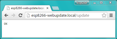
| 6. Now press “Choose File” in web browser, go to directory identified in step 5 above, find the file “WebUpdater.cpp.bin” and upload it. If upload is successful you will see “OK” on web browser like below. | 6. Now press “Choose File” in web browser, go to directory identified in step 5 above, find the file “WebUpdater.cpp.bin” and upload it. If upload is successful you will see “OK” on web browser like below. | ||
| - |  | + |  |
| Module will reboot that should be visible on Serial Monitor: | Module will reboot that should be visible on Serial Monitor: | ||
| - |  | + | 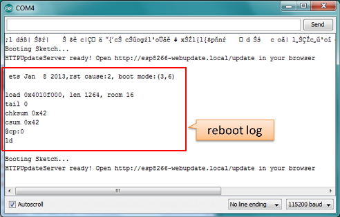 |
| | | ||
| Just after reboot you should see exactly the same message ``` HTTPUpdateServer ready! Open http:// esp8266-webupdate.local /update in your browser``` like in step 3. This is because module has been loaded again with the same code – first using serial port, and then using OTA. | Just after reboot you should see exactly the same message ``` HTTPUpdateServer ready! Open http:// esp8266-webupdate.local /update in your browser``` like in step 3. This is because module has been loaded again with the same code – first using serial port, and then using OTA. | ||
| Line 463: | Line 461: | ||
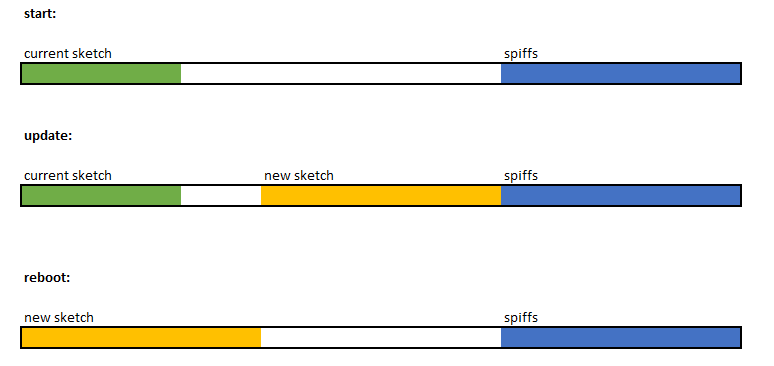
| - the new sketch is started. | - the new sketch is started. | ||
| - |  | + |  |
ota-over-the-air-esp8266.txt · Last modified: 2016/06/15 15:41 by admin