- Mon Aug 01, 2016 10:40 am
#51890
martinayotte wrote:Instead of the 10uF, I would rather use a 47uF or even a 100uF to satisfy the surges.
If I have the space I would include more capacitance as Martin suggested. But I would also add smaller value capacitors in parallel to the larger one.
When I was trying to resolve the power supply issues that I had I had tried a number of things including adding higher value capacitance to supply the surge currents. And I was disappointed that adding capacitance was not enough to prevent the drops on the 3.3 volt line. I had expected it to work but the oscilloscope image showed that it didn't. I wanted to take screen captures of the scope's images but the serial port on the scope wasn't working at the time.
For breadboard use I have been using this.
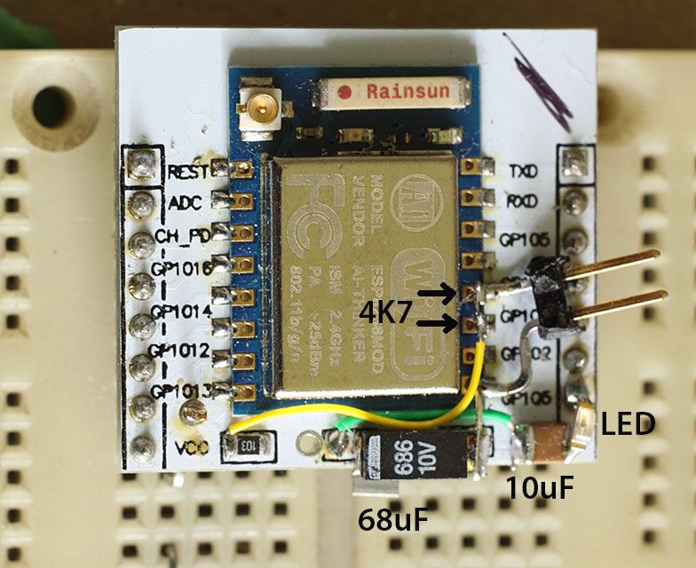
This has the ESP07 module. I normally use the ESP12 on the same board with modifications.
On a recent project I did a prototype layout pcb. I had a small section of board that was clear so I included my own version of a breakout board like the above one. I made it narrower so there would be access to a connection point for each pin.
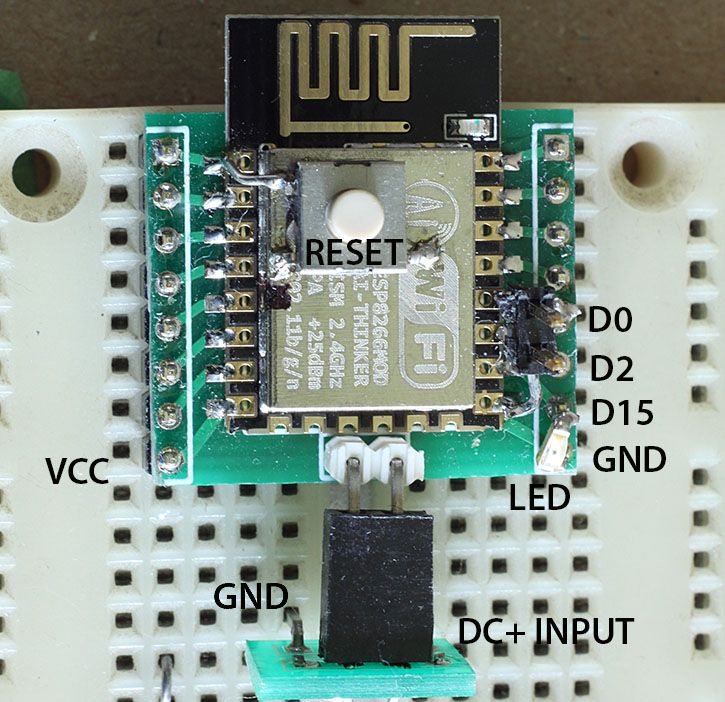
I soldered a reset switch to the top of the shield. I have an LED (with series resistor) soldered to D15. I have a couple of shorting pins used to connect D0 to GND.
On the bottom of the board I have the following.
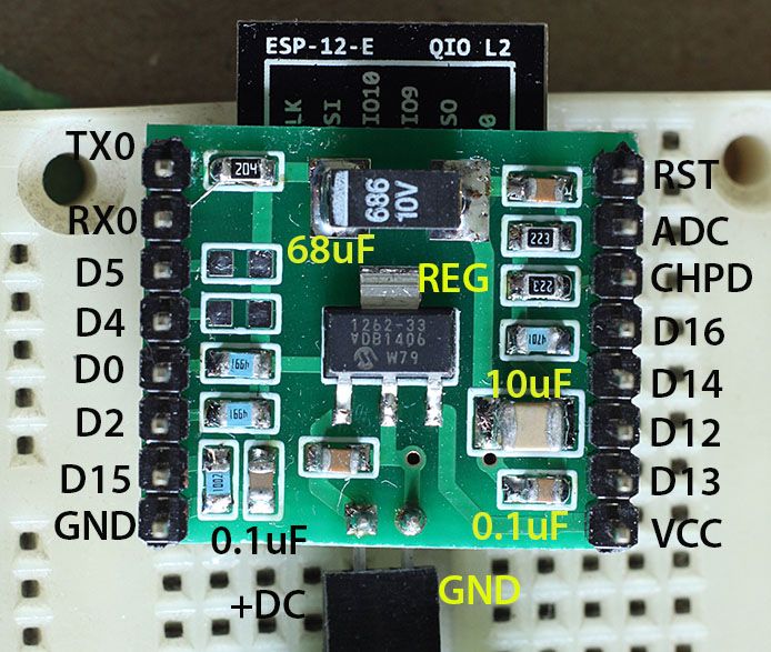
I have a 3.3 volt regulator for the power to VCC. I have a 68uF capacitor, a 10uF ceramic capacitor, and two 0.1uF capacitors on the output of the regulator. And I have a few pull up resistors, and pull down for D15.
The components were chosen so they would not be any higher than the plastic spacer on the terminal pins. So the board sits flat in the breadboard when the ESP module is face up. For cost reasons the board is only two layer. If it was a 4 layer board then I would have used VCC and GND planes in the internal layers. Circuit board layout is always a compromise.
I can use the above board in a breadboard or I can just apply power to the two pins in the middle and it has all it needs to run.
Rudy
Last edited by rudy on Mon Nov 21, 2016 7:24 pm, edited 1 time in total.


