
- Mon May 25, 2015 1:27 am
#18367
Here is my method of mounting `esp8266`'s, specifically `ESP-03` on a breadboard without the use of a breakout board. This material also appears on my blog
First, find some 110/220V wire and cut a piece of it off.
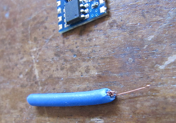
Into your breadboard put some headers and push the gold pins all the way in. Then solder the individual strands to each pin. First one...
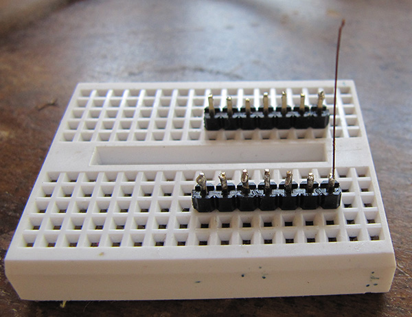
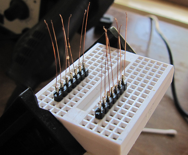
and then, the rest of them.
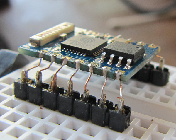
Tack on your `ESP-03` by one of the strands. Recommended: first connect pin 4 out of 7 with slot 4 out of 7. In the middle, basically.
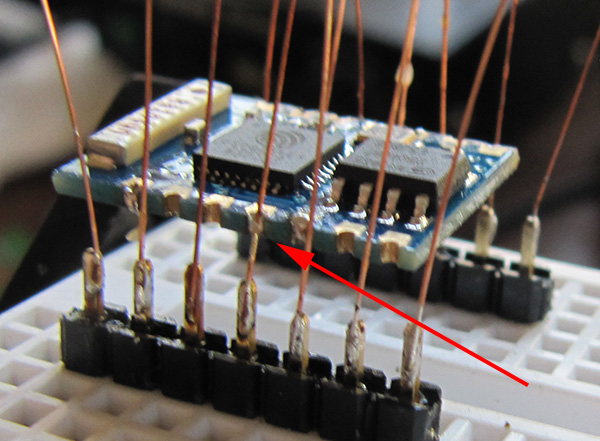
Complete one side, and bend the PCB down a little bit, like you see in this picture
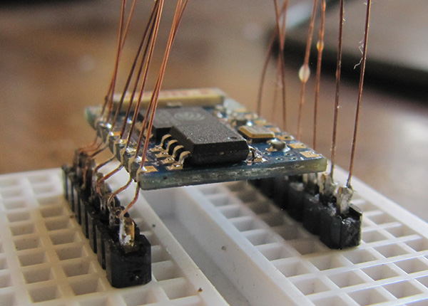
Now solder in the other side, again beginning from the center.
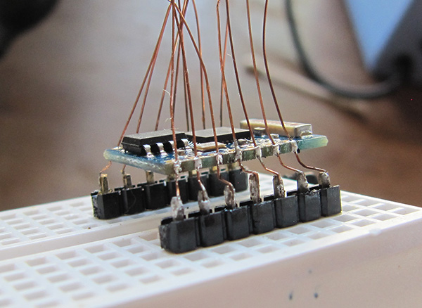
Trim the excess and take some time to savor the result ;P
But we are not done yet. Now, we have wire up the chip. Use the following schematic. I originally saw it in this thread. Hat tip to mano1979.
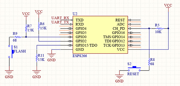
The observant reader is probably screaming at me right now that that not all of those pins in the schematic above are available in on the `ESP-03`, and indeed the schematic shows `ESP-07`, but don't mind those other pins - we're not gonna use them anyways. Just connect the used pins as they are located on the `ESP-03`. In place of 15K resistors you can use 10K.
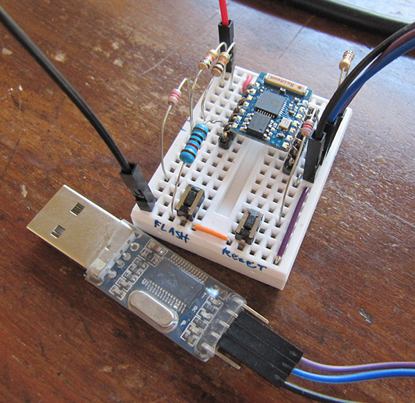
Also notice that the reset pin is not available by default, so instead we rely on grounding CH_PD, which in my experience achieves the same effect. At this point you should have something that looks like this:
First, find some 110/220V wire and cut a piece of it off.
Into your breadboard put some headers and push the gold pins all the way in. Then solder the individual strands to each pin. First one...
and then, the rest of them.
Tack on your `ESP-03` by one of the strands. Recommended: first connect pin 4 out of 7 with slot 4 out of 7. In the middle, basically.
Complete one side, and bend the PCB down a little bit, like you see in this picture
Now solder in the other side, again beginning from the center.
Trim the excess and take some time to savor the result ;P
But we are not done yet. Now, we have wire up the chip. Use the following schematic. I originally saw it in this thread. Hat tip to mano1979.
The observant reader is probably screaming at me right now that that not all of those pins in the schematic above are available in on the `ESP-03`, and indeed the schematic shows `ESP-07`, but don't mind those other pins - we're not gonna use them anyways. Just connect the used pins as they are located on the `ESP-03`. In place of 15K resistors you can use 10K.
Also notice that the reset pin is not available by default, so instead we rely on grounding CH_PD, which in my experience achieves the same effect. At this point you should have something that looks like this:


